This thread has been locked.

If you have a related question, please click the "Ask a related question" button in the top right corner. The newly created question will be automatically linked to this question.

LAUNCHXL-F28379D: SDFM PWM sync configuration

Part Number: LAUNCHXL-F28379D
Other Parts Discussed in Thread: TMS320F28379D, C2000WARE

Hello Experts,

I am facing an issue in syncing pwm channels to the SDFM module,

Reading the technical reference manual of TMS320F28379D , it does not give much information. It just says that when SDSYNCEN is enabled, PWM11 will reset SDFM1 data filter and PWM12 will reset SDFM2 

First off, what is "PWM11" and "PWM12"? Does PWM11 mean EPWM1 Module Channel A, and PWM12 mean EPWM1 Module Channel B?

How do I change it so that it can sync to another EPWM module, example EPWM1.CMPA should reset SDFM1 and EPWM4.CMPB should reset SDFM2?

I see in the sdfm.h file of C2000WARE (ti\c2000\C2000Ware_4_01_00_00\driverlib\f28004x\driverlib) there is a function which does this: 

//*****************************************************************************
//
//! Values that can be passed to SDFM_setPWMSyncSource(),as the
//! \e syncSource parameter.
//
//*****************************************************************************
typedef enum
{
   SDFM_SYNC_PWM1_SOCA = 0,    //!< SDFM sync source is PWM1 SOCA
   SDFM_SYNC_PWM1_SOCB = 1,    //!< SDFM sync source is PWM1 SOCB
   SDFM_SYNC_PWM2_SOCA = 4,    //!< SDFM sync source is PWM2 SOCA
   SDFM_SYNC_PWM2_SOCB = 5,    //!< SDFM sync source is PWM2 SOCB
   SDFM_SYNC_PWM3_SOCA = 8,    //!< SDFM sync source is PWM3 SOCA
   SDFM_SYNC_PWM3_SOCB = 9,    //!< SDFM sync source is PWM3 SOCB
   SDFM_SYNC_PWM4_SOCA = 12,   //!< SDFM sync source is PWM4 SOCA
   SDFM_SYNC_PWM4_SOCB = 13,   //!< SDFM sync source is PWM4 SOCB
   SDFM_SYNC_PWM5_SOCA = 16,   //!< SDFM sync source is PWM5 SOCA
   SDFM_SYNC_PWM5_SOCB = 17,   //!< SDFM sync source is PWM5 SOCB
   SDFM_SYNC_PWM6_SOCA = 20,   //!< SDFM sync source is PWM6 SOCA
   SDFM_SYNC_PWM6_SOCB = 21,   //!< SDFM sync source is PWM6 SOCB
   SDFM_SYNC_PWM7_SOCA = 24,   //!< SDFM sync source is PWM7 SOCA
   SDFM_SYNC_PWM7_SOCB = 25,   //!< SDFM sync source is PWM7 SOCB
   SDFM_SYNC_PWM8_SOCA = 28,   //!< SDFM sync source is PWM8 SOCA
   SDFM_SYNC_PWM8_SOCB = 29    //!< SDFM sync source is PWM8 SOCB
} SDFM_PWMSyncSource;


static inline void
SDFM_setPWMSyncSource(uint32_t base, SDFM_FilterNumber filterNumber,
                      SDFM_PWMSyncSource syncSource)

But in the f2837xd folder (ti\c2000\C2000Ware_4_01_00_00\driverlib\f2837xd\driverlib) , the above function seems to be missing.

This are my SDFM settings:

void init_sdfm(uint32_t base)   //SDFM1_BASE
{
    //
    // SD1 -> mySDFM0 Pinmux
    //
    GPIO_setPinConfig(GPIO_123_SD1_C1);
    GPIO_setQualificationMode(123, GPIO_QUAL_3SAMPLE);
    GPIO_setPinConfig(GPIO_122_SD1_D1);
    GPIO_setQualificationMode(122, GPIO_QUAL_3SAMPLE);

    Interrupt_register(INT_SD1, INT_mySDFM0_ISR);
    Interrupt_enable(INT_SD1);

    //
    // Input Control Unit
    //
    // Configure Input Control Unit: Modulator Clock rate = Modulator data rate
    //
    SDFM_setupModulatorClock(base, SDFM_FILTER_1, SDFM_MODULATOR_CLK_EQUAL_DATA_RATE);

    //
    // Configure comparator filter settings
    //
    SDFM_configComparator(base, (SDFM_FILTER_1 | SDFM_FILTER_SINC_1 | SDFM_SET_OSR(0)), SDFM_THRESHOLD(0,0));

    //
    // Configure data filter settings
    //
    SDFM_configDataFilter(base, (SDFM_FILTER_1 | SDFM_FILTER_SINC_3 | SDFM_SET_OSR(128)), (SDFM_FILTER_ENABLE | SDFM_DATA_FORMAT_16_BIT | SDFM_SHIFT_VALUE(7)));

    // Master Filter Enable
    SDFM_enableMasterFilter(base);

    //
    // Configure SDSYNC (Filter reset from PWM)
    //
    SDFM_enableExternalReset(base, SDFM_FILTER_1);
    //SDFM_disableExternalReset(base, SDFM_FILTER_1);

    SDFM_enableInterrupt(base, SDFM_FILTER_1,
                (SDFM_MODULATOR_FAILURE_INTERRUPT |
                 SDFM_DATA_FILTER_ACKNOWLEDGE_INTERRUPT));
    SDFM_disableInterrupt(base, SDFM_FILTER_1,
                (SDFM_HIGH_LEVEL_THRESHOLD_INTERRUPT |
                 SDFM_LOW_LEVEL_THRESHOLD_INTERRUPT));

    //
    // Enable master interrupt so that any of the filter interrupts can trigger
    // by SDFM interrupt to CPU
    //
    SDFM_enableMasterInterrupt(SDFM1_BASE);
}

EPWM_SignalParams pwmSignal = {
                               10000,                       //!< Desired Signal Frequency(in Hz)
                               0.5f,                        //!< Desired ePWMxA Signal Duty
                               0.5f,                        //!< Desired ePWMxB Signal Duty
                               true,                        //!< Invert ePWMxB Signal if true
                               DEVICE_SYSCLK_FREQ,          //!< SYSCLK Frequency(in Hz)
                               SYSCTL_EPWMCLK_DIV_2,        //!< EPWM Clock Divider
                               EPWM_COUNTER_MODE_UP_DOWN,   //!< Time Base Counter Mode
                               EPWM_CLOCK_DIVIDER_1,        //!< Time Base Counter Clock Divider
                               EPWM_HSCLOCK_DIVIDER_1       //!< Time Base Counter HS Clock Divider
};

void pwm_init(uint32_t base)
{
    EPWM_configureSignal(base, &pwmSignal);
    EPWM_setSyncOutPulseMode(base, EPWM_SYNC_OUT_PULSE_ON_COUNTER_ZERO);
    SysCtl_enablePeripheral(SYSCTL_PERIPH_CLK_TBCLKSYNC);
    Interrupt_enable(INT_EPWM4);
}

Kindly Help.

  • First off, what is "PWM11" and "PWM12"? Does PWM11 mean EPWM1 Module Channel A, and PWM12 mean EPWM1 Module Channel B?

    The F2837x device has 12 PWM modules. The note specifically references PWM11 and PWM12.

    How do I change it so that it can sync to another EPWM module, example EPWM1.CMPA should reset SDFM1 and EPWM4.CMPB should reset SDFM2?

    This is not possible. Only PWM11 and PWM12 can be used.

    I see in the sdfm.h file of C2000WARE (ti\c2000\C2000Ware_4_01_00_00\driverlib\f28004x\driverlib) there is a function which does this:

    This only applies to the F28004x device, as the path suggest. On F2837x you are limited to PWM11 and PWM12.

  • Hi Guss, Thanks for the clarification, 

    Unfortunately we cannot use PWM11 and PWM12 as the hardware PCB is already routed to use other PWM pins.

    Currently we are using 3 PWM modules to run a motor EPWM1,2 and 3. If we need to manually sync with PWM1, can we do it like this:

    I am getting correct data, but wanted to confirm if this is the most efficient way to do it , if we cannot use SDSYNC Event,

    __interrupt void epwm1ISR(void)
    {
        pwm_counter++;
    
        SDFM_enableMasterFilter(SDFM1_BASE);
        while(!SDFM_getNewFilterDataStatus(SDFM1_BASE, SDFM_FILTER_1)) {}
        sdfmGarbageCount++;
        if(sdfmGarbageCount > 1)
        {
            sdfmGarbageCount = 0;   //The first two samples of the Sinc3 filter are incorrect
        }
        else
        {
            filter1Result = ((int16_t) (SDFM_getFilterData(SDFM1_BASE,SDFM_FILTER_1) >> 16U));
            SDFM_disableMasterFilter(SDFM1_BASE);
        }
        //
        // Clear INT flag for this timer
        //
        EPWM_clearEventTriggerInterruptFlag(EPWM1_BASE);
    
        //
        // Acknowledge this interrupt to receive more interrupts from group 3
        //
        Interrupt_clearACKGroup(INTERRUPT_ACK_GROUP3);
    }
    

  • AK,

    I don't see anything wrong with your approach. One other approach you could consider is to EPWM11/12 and use the PWM SYNC feature to keep these in sync with PWM1. You'd have to configure PWM11/12 exactly as PWM1, including updating with the same CMPC/D values. You don't have to bring out the PWM11/12 outputs to the MCU pins. One downside here is that there isn't a way to sync PWM11/12 to PWM2. Just something to consider. 

  • Thanks Gus, I understand.

    One more clarification I need from you. Does the SDFM_DATA_FILTER_ACKNOWLEDGE_INTERRUPT generate for every filter channel? Is there a way I can get the status of all the channels at once, instead of checking each filter channel individually..

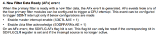
  • AK, the SDFM_DATA_FILTER_ACKNOWLEDGE_INTERRUPT macro is used to enable the "new filter data" interrupt for individual data filters. Per TRM:

    You can also see in the C2000ware header file, sdfm.h, that SDFM_DATA_FILTER_ACKNOWLEDGE_INTERRUPT is used to enable the filter acknowledge interrupt.

    //*****************************************************************************
    //
    //! Enable SDFM interrupts.
    //!
    //! \param base is the base address of the SDFM module
    //! \param filterNumber is the filter number.
    //! \param intFlags is the interrupt source.
    //!
    //! This function enables the low threshold , high threshold or modulator
    //! failure interrupt as determined by intFlags for the filter specified
    //! by filterNumber.
    //! Valid values for intFlags are:
    //!  SDFM_MODULATOR_FAILURE_INTERRUPT , SDFM_LOW_LEVEL_THRESHOLD_INTERRUPT,
    //!  SDFM_HIGH_LEVEL_THRESHOLD_INTERRUPT,SDFM_DATA_FILTER_ACKNOWLEDGE_INTERRUPT
    //!
    //! \return None.
    //
    //*****************************************************************************
    static inline void
    SDFM_enableInterrupt(uint32_t base, SDFM_FilterNumber filterNumber,
                         uint16_t intFlags)
    {
        uint16_t offset;
    
        ASSERT(SDFM_isBaseValid(base));
    
        offset = (uint16_t)filterNumber * 16U;
    
        EALLOW;
    
        //
        // Low, high threshold, Modulator failure
        //
        if((intFlags & (SDFM_MODULATOR_FAILURE_INTERRUPT |
                        SDFM_LOW_LEVEL_THRESHOLD_INTERRUPT |
                        SDFM_HIGH_LEVEL_THRESHOLD_INTERRUPT)) != 0U)
        {
            //
            // Set IEL or IEH or MFIE bit of SDFM_O_SDCPARMx
            //
            HWREGH(base + SDFM_O_SDCPARM1 + offset) |=
                    (intFlags & (SDFM_MODULATOR_FAILURE_INTERRUPT |
                                 SDFM_LOW_LEVEL_THRESHOLD_INTERRUPT |
                                 SDFM_HIGH_LEVEL_THRESHOLD_INTERRUPT));
        }
    
        //
        // Data filter acknowledge interrupt
        //
        if((intFlags & SDFM_DATA_FILTER_ACKNOWLEDGE_INTERRUPT) != 0U)
        {
            HWREGH(base + SDFM_O_SDDFPARM1 + offset) |= SDFM_SDDFPARM1_AE;
        }
        EDIS;
    }

    To view the status of all the data filters you can use the SDIFLG register.

  • Thanks Gus , It is clear to me now. Much Appreciated.