This thread has been locked.

If you have a related question, please click the "Ask a related question" button in the top right corner. The newly created question will be automatically linked to this question.

TMS320F280049C: F280049C, DRV8320RS, BLDC Motor Control Problem

Part Number: TMS320F280049C
Other Parts Discussed in Thread: DRV8320, LAUNCHXL-F280049C, C2000WARE

Hello everyone,

I use the LAUNCHXL-F280049C development board and the DRV8320 EVM Evaluation Module as described inLAB "is01-13"(MotorControl InstaSPIN SDK)

Unfortunately i don't know three phase BLDC motor spec(volatge, maximum current and so on),, so i want to drive the motor using a reference voltage(12V) and to identificate the motor parameters.

is01_intro_hal -> ok
is02_offset_gain_cal -> ok
is03_hardware_test -> NG

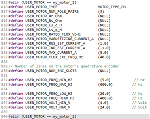
-my motor setting(user.h)

I checked the PWMDAC when the motor was not connected through the first step.(0 - 3.3V)
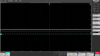
But If i set the variable "motorVars.flagRunIdentAndOnLine" equal to 1, i have a problem is not driven the motor.

More specifically,
ADC Signal is temporarily observed through an oscilloscope. However, After overcurrent flows, ADC signal is not observed and the Variable "motorVars.flagRunIdentAndOnLine" change automatically to 0.
i think that the PWM and ADC modules do not operate because a trip condition occurs due to OverCurrent.
Of course, this is my personal opinion.

also, If LAB is performed after connecting the motor power, the motor driver board(DRV8320RS and Inductor) generates severe heat.

I have two inquiries.
1. Why the motor did not drive with an open loop(set the variable "motorVars.flagRunIdentAndOnLine" equal to 1)

2. Reasons for severe fever and How to problem of severe fever.

  • You need to configure the right v/f profile for is03_hardware_test according to the motor. This lab run the motor with open-loop to verify the current and voltage sensing circuit. The v/f open loop mode doesn't need to know the exact motor parameters, just need to know the rated voltage and speed of the motor.

    The incorrect v/f profile my cause the over-current fault to stop the motor.

    Please take a look at  the lab guide to run the example labs, the guide at the folder below.

    \ti\c2000\C2000Ware_MotorControl_SDK_<version>\solutions\common\sensorless_foc\docs\labs

  • ok, i will check the rated voltage and speed of the motor. 

    and, i have another question...

    I can't find source file about the gpio configuration and external circuit initialization configuration. i want check the chip initialization code.

    please tell me how to check it.

  • You can find all of the source about the C2000 peripherals configuration including GPIO in C2000Ware.

    C:\ti\c2000\C2000Ware_MotorControl_SDK_<version>\c2000ware\driverlib\f28004x

  • hi, Yanming Luo

    After changing the motor profile, I was able to output the three-phase voltage and current. thanks.

    Additionally, I have two questions.

    1. Looking at other users' forums about PWMDAC Module, is it true that EV Board(280049+drv8320) cannot use the PWMDAC Module?

    2. If It cannot use PWMDAC Module, can I not proceed with signal_chain_test(Current Closed Loop Control)?

  • 1. Looking at other users' forums about PWMDAC Module, is it true that EV Board(280049+drv8320) cannot use the PWMDAC Module?

    There is not a RC filter on Launchxl-f280049 for PWMDAC.

    2. If It cannot use PWMDAC Module, can I not proceed with signal_chain_test(Current Closed Loop Control)?

    You can use the datalog. Or you don't need to run the lab01/02/03 since you are using the kits supported in the lab. These 3 labs are just for verifying a new board design by the customer.