This thread has been locked.

If you have a related question, please click the "Ask a related question" button in the top right corner. The newly created question will be automatically linked to this question.

TMS320F28065: How to tune pid controller parameters?

Part Number: TMS320F28065
Other Parts Discussed in Thread: CONTROLSUITE, C2000WARE-MOTORCONTROL-SDK, C2000WARE

Hi TI experts,

I want to drive a PMSM motor using C2000 microcontrollers.

I am using foc algorithm for controling the motor. 

I have designed a custom board. I started this this application note:

C:\ti\controlSUITE\development_kits\DRV8312-C2-KIT_v128\PM_Sensorless

In build level 4 after tuning pid controllers’ parameters, the current waveforms of phase A & B should appear as the following image:


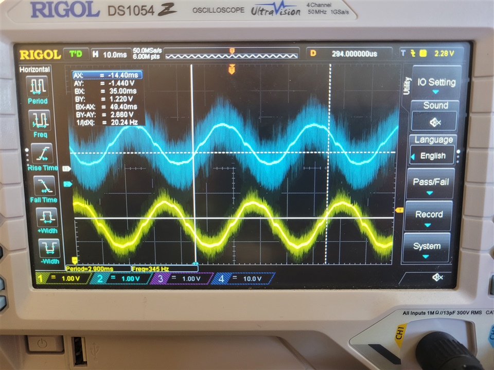
However, when I check the waveforms, they are not completely sine waves. Here is the current waveforms of phase A&B.


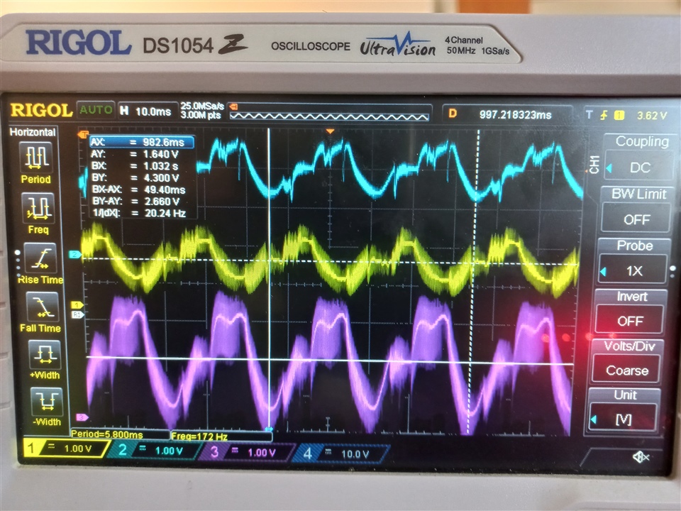
The blue one is current waveform of phase A (using PWMDAC), the yellow one is current waveform of phase B (using PWMDAC) and purple one is also current waveform of phase A (using scope probe on the output of current sensor).

Can I consider these wave  as sine waveform? I’m afraid that I have not tuned PID controllers’ parameters (Iq, Id) correctly.

Thank you in advance.


  • It's not only related to the PI regulator, it's also dependent on the motor parameters and control parameters for the SMO.

    Please take a look at the application note in the folder you mentioned above.

  • Thank you for the reply. I'm in level4 of the application note and there is no smo module.

    I have read the document multiple times and unfortunately couldn't figure out how to solve this problem. 

  • Try to tune the reference torque current and speed as below since you are running the motor with open loop.

    _iq IdRef = _IQ(0.0); // Id reference (pu)
    _iq IqRef = _IQ(0.2); // Iq reference (pu)
    _iq SpeedRef = _IQ(0.25); // Speed reference (pu)

    Recommend that you may try to use the latest motor control lab with InstaSPIN-FOC as below if you just start the evaluation and want to run a motor with sensorless-FOC.

    You may refer to the lab for the newer C2000 device in motor control SDK. The universal motor control lab is available in the current MCSDK, which can support a set of hardware kits and control algorithms for BLDC/PMSM drive. The kits include LAUNCHXL-F280025C, LAUNCHXL-F280039CLAUNCHXL-F2800137 with BOOSTXL-DRV8323RS, BOOSTXL-DRV8323RH, DRV8353Rx-EVMBOOSTXL-3PHGANINV, DRV8316REVM, or  DRV8329AEVM inverter board for low voltage motor (max: 100Vdc) . TMDSCNCD280025C, TMDSCNCD2800137 , or TMDSCNCD280039C with TMDSHVMTRINSPIN inverter board and TMDSADAP180TO100 for high voltage motor (max 350Vdc). And The control algorithms include sensorless InstaSPIN-FOC with FAST, Sensorless-FOC with eSMO, Sensored-FOC with incremental encoder, Sensored-FOC with hall sensor.

    C2000WARE-MOTORCONTROL-SDK: https://www.ti.com/tool/C2000WARE-MOTORCONTROL-SDK

    Universal Project and Lab User’s Guide: https://www.ti.com/lit/spruj26

    Example lab project at the folder: C:\ti\c2000\C2000Ware_MotorControl_SDK_<version>\solutions\universal_motorcontrol_lab\f28002x

    or                                                         C:\ti\c2000\C2000Ware_MotorControl_SDK_<version>\solutions\universal_motorcontrol_lab\f28003x

    or                                                         C:\ti\c2000\C2000Ware_MotorControl_SDK_<version>\solutions\universal_motorcontrol_lab\f280013x

  • Thank you for your answer. It helped a lot. 

    Now I am using this this application project:

    C:\ti\controlSUITE\development_kits\HVMotorCtrl+PfcKit_v2.1\HVPM_Sensorless_2833x

    the current waveforms of phase A&B is illustrated in the following image.

    I have another question. In level 2B of this application note, it says:

    "Run the system with default VdTesting, VqTesting and SpeedRef and gradually increase VdTesting and VqTesting values. Meanwhile, watch the current waveforms in the graph window. Keep increasing until you notice distorted current waveforms and write down the maximum allowed VdTesting and VqTesting values. Make sure that these values are consistent with expected d-q current component maximums while running the motor. After this build level, PI outputs will automatically generate the voltage reference and determine the PWM duty cycle depending on the d-q current demand, therefore set pi_id.Umax/min and pi_iq.Umax/min according to recorded VdTesting and VqTesting values respectively."

    How much distortion is acceptable? Basically, even with default values of VdTesting and VqTesting, the current waveforms are not ideal sine waves. 

    Thank you.

  • There is no a specfic value for you, that depends on the motor. This level (2 or 2B) runs the motor with open-loop to verify the current and voltage sensing. You can compare the sensign current to the measured current with current probe.