


Other Parts Discussed in Thread: MOTORWARE
Hello Ti or another user that may have an opinion to this,
I have a question about the angle delay compensation. When comparing the Motorware, MCSDK-Instaspin-FOC (49c) and servo_drive_with_can(universal_lab) for example, I get 3 different values for the angle compensation, which I don’t understand. Is there anything wrong with my calculations?
Motorware and servo_drive_with_can are very similar, except Motorware is multiplying the angleDelta by a comp factor. For the MCSDK-Instapsin-FOC I get only the half compared to the servo_drive_with_can.
Here are the calculations for PWM_freq = 20kHz, Motor_freq = 500Hz
Motorware: (angle_pu = 0-1 -> angle = 0-2pi)
angleDelta_pu = fm_pu * Fullscale_freq / PWM_freq
fm_pu = 1 ; Fullscale_freq = 500Hz ; PWM_freq = 20000 Hz
angleDelta_pu = 1*500/20000 = 0.025
angleDelta_rad = 0.025*2*pi = 0.157rad -> 9°
angleComp = angleDelta_rad * (1 + PWM_ticks_per_ISR * 0.5)
PWM_ticks_per_ISR = 1 -> angleComp = 9° * (1 + 1 * 0.5) = 13.5°
PWM_ticks_per_ISR = 3 -> angleComp = 9° * (1 + 3 * 0.5) = 22.5°
MCSDK-Instapsin-FOC for 280049c :
angleDelta_rad = angleDelayed_sf_sec * fm_rad/s
angleDelta_rad = 0.5 * 1/ PWM_freq * PWM_ticks_per_ISR * fm_rad/s
fm_rad/s = 500Hz * 2 * pi = 3141rad/s ; PWM_freq = 20000 Hz
angleDelta_rad = 0.5 * 1/ 20000 * PWM_ticks_per_ISR * 3141
PWM_ticks_per_ISR = 1 -> angleDelta_rad = 0.5 * 1/ 20000 * 1 * 3141 = 0.07852rad -> 4.5°
PWM_ticks_per_ISR = 3 -> angleDelta_rad = 0.5 * 1/ 20000 * 3 * 3141 = 0.2355rad -> 13.5°
servo_drive_with_can:
angleDelta_rad = freq_hz * angleDeltaFactor
angleDelta_rad = freq_hz * 1/PWM_freq * PWM_ticks_per_ISR * 2* pi
freq_hz = 500Hz ; PWM_freq = 20000 Hz
PWM_ticks_per_ISR = 1 -> angleDelta_rad = 500 * 1/20000 * 1 * 2* pi = 0.157rad -> 9°
PWM_ticks_per_ISR = 3 -> angleDelta_rad = 500 * 1/20000 * 3 * 2* pi = 0.471rad -> 27°
For me, the Motorware angleDelta makes only sense if PWM_ticks_per_ISR = 1.
The angleDelta in servo_drive_with_can makes sense for PWM_ticks_per_ISR = 1 and 3. But here the average PWM voltage isn't considerd.
The angleDelta in MCSDK-Instapsin-FOC is just the half of the servo_drive_with_can example.
Why is this so, why are there so many differences?
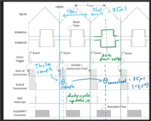
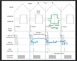
I would like to use the formula below, what do you think of that? (PWM_TICK_PER_ISR = 1) Because of the delay from the PWM duty cycle update, I must add one PWM cycle as an angle delay. Here I’m not 100% sure, but I would add another half of PWM to get to the average PWM voltage, is this a good idea? (Like in the first picture below). The other option would be to set the corrected angle on the beginning of the PWM period. What is better?
My formula would look like this:
angleDelta_rad = Freq_hz_motor * 2pi * PWM_ticks_per_ISR/ PWM_freq * ( 1 + 0.5 ) (in rad)
PWM_ticks_per_ISR = 1 -> angleDelta_rad = 0.2355rad -> 13.5°
PWM_ticks_per_ISR = 3 -> angleDelta_rad = 0.7068rad -> 40.5°
Here is a picture, first PWM ticks = 1 and the second picture PWM ticks = 3:
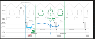
The same but PWM_ticks_per_ISR = 3.
Here I add three pwm cycles and the half of three for the average voltage.
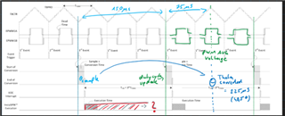
I also drew the sample angles and the corrected angles for the calculations in the examples.
Picture for motorware:
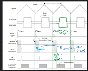
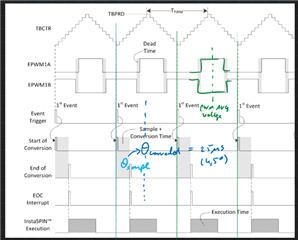
mcsdk Instaspin-foc for 280049c :
sensored foc CAN drive:
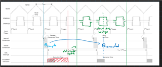
But I also not sure if PWM_ticks_per_ISR = 3, when the PWM duty cycle gets updated. If the duty cycle gets updated after the three PWM cycles, then my formula for PWM_ticks_per_ISR = 3 should be ok. If this is not the case and the PWM value gets updated, whenever the FAST Estimator is finished and writes the PWM values in the CMPA, then I must overthink my formula for PWM_ticks_per_ISR = 3. (I think I would have to consider the execution time in relation to the PWM frequency). Like the picture below:
When is the PWM duty cycle updated?
(But as mentioned above I’m not 100% sure if I should set the corrected angle in the middle of the PWM period)
Thank you in advance,
Daniel
