Hi,
I am working on a project with HRPWM.
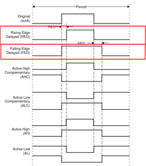
In this project we want to be quite precise in the first PWM values. To do this we use the DEADBAND which allows us to use the HRPWM from 1% of the duty cycle while losing the precision at 100% of PWM
I generate a HRPMW4A and a HRPMW4B with the DEADBAND, the HRPMW4B is generated from the HRPWM4A and is inverted.
Using the HRPWM I noticed that the delay between the rising edge of PWMxA and the falling edge of PWMxB and vice versa changes if the CMPAHR or CMPBHR values are changed.
In my project I should have a delay of 100ns, this value does not change with the different values of CMPA and CMPB but by changing CMPAHR and CMPBHR it can go down to 91ns.
I have seen in other posts that the HRPWM comes after the DEADBAND which might explain why this only applies to CMPxHR and not CMPx.
Is there a way to avoid this while keeping the HRPWM for duty with the DEADBAND?
Here is my code.
//#############################################################################
//
// FILE:    gpio_ex1_setup.c
//
// TITLE:   Device GPIO Setup
//
//! \addtogroup driver_example_list
//! <h1> Device GPIO Setup </h1>
//!
//! Configures the device GPIO into two different configurations
//! This code is verbose to illustrate how the GPIO could be setup.
//! In a real application, lines of code can be combined for improved
//! code size and efficiency.
//!
//! This example only sets-up the GPIO. Nothing is actually done with
//! the pins after setup.
//!
//! \b In \b general: \n
//!  - All pullup resistors are enabled.  For ePWMs this may not be desired.
//!  - Input qual for communication ports (CAN, SPI, SCI, I2C) is asynchronous
//!  - Input qual for Trip pins (TZ) is asynchronous
//!  - Input qual for eCAP and eQEP signals is synch to SYSCLKOUT
//!  - Input qual for some I/O's and __interrupts may have a sampling window
//
//#############################################################################
//
//
// $Copyright:
// Copyright (C) 2022 Texas Instruments Incorporated - http://www.ti.com/
//
// Redistribution and use in source and binary forms, with or without
// modification, are permitted provided that the following conditions
// are met:
//
//   Redistributions of source code must retain the above copyright
//   notice, this list of conditions and the following disclaimer.
//
//   Redistributions in binary form must reproduce the above copyright
//   notice, this list of conditions and the following disclaimer in the
//   documentation and/or other materials provided with the
//   distribution.
//
//   Neither the name of Texas Instruments Incorporated nor the names of
//   its contributors may be used to endorse or promote products derived
//   from this software without specific prior written permission.
//
// THIS SOFTWARE IS PROVIDED BY THE COPYRIGHT HOLDERS AND CONTRIBUTORS
// "AS IS" AND ANY EXPRESS OR IMPLIED WARRANTIES, INCLUDING, BUT NOT
// LIMITED TO, THE IMPLIED WARRANTIES OF MERCHANTABILITY AND FITNESS FOR
// A PARTICULAR PURPOSE ARE DISCLAIMED. IN NO EVENT SHALL THE COPYRIGHT
// OWNER OR CONTRIBUTORS BE LIABLE FOR ANY DIRECT, INDIRECT, INCIDENTAL,
// SPECIAL, EXEMPLARY, OR CONSEQUENTIAL DAMAGES (INCLUDING, BUT NOT
// LIMITED TO, PROCUREMENT OF SUBSTITUTE GOODS OR SERVICES; LOSS OF USE,
// DATA, OR PROFITS; OR BUSINESS INTERRUPTION) HOWEVER CAUSED AND ON ANY
// THEORY OF LIABILITY, WHETHER IN CONTRACT, STRICT LIABILITY, OR TORT
// (INCLUDING NEGLIGENCE OR OTHERWISE) ARISING IN ANY WAY OUT OF THE USE
// OF THIS SOFTWARE, EVEN IF ADVISED OF THE POSSIBILITY OF SUCH DAMAGE.
// $
//#############################################################################

//
// Included Files
//
#include "driverlib.h"
#include "device.h"
#include "sfo_v8.h"

void epwm_gpio_init(void);
void epwm_init_module(void);
void hrpwm_init_module(void);

#define EPWM_CMPC_VALUE   0U                        // Set to 0 here (we want to send to the beginning of period)
#define EPWM_SYNC_EVENT_COUNT   1U                  // Send frame every period here (can go up to 15)

#define PWMCLK     100U   // PWM module clock in Mhz
#define PWM_FREQ   100U   // Transmission PWM frequency in Khz

//
//  SFO calibration flags
//
#define STATUS_SUCCESS    1
#define STATUS_FAIL       0


#define ADC_NORM   (float)0.00048828125

//
//  SFO calibration flags
//
#define STATUS_SUCCESS    1
#define STATUS_FAIL       0


float32_t duty      = 0;
uint32_t dutyFine   = 0;

uint16_t status;

//
// Global variable used by the SFO library
// Result can be used for all HRPWM channels
// This variable is also copied to HRMSTEP
// register by SFO() function.
//
int MEP_ScaleFactor;

//
// Used by SFO library (ePWM[0] is a dummy value that isn't used)
//
volatile uint32_t ePWM[2] = {0, EPWM4_BASE};

uint16_t period = (PWMCLK / (float)PWM_FREQ) * 1000U;

//
// Main
//
void main(void)
{
    //
    // Initializes system control, device clock, and peripherals
    //
    Device_init();

    //
    // Initializes PIE and clear PIE registers. Disables CPU interrupts.
    // and clear all CPU interrupt flags.
    //
    Interrupt_initModule();

    //
    // Initialize the PIE vector table with pointers to the shell interrupt
    // Service Routines (ISR).
    //
    Interrupt_initVectorTable();

    epwm_gpio_init();

    status = SFO_INCOMPLETE;
    while(status == SFO_INCOMPLETE)
    {
        status = SFO();
        if(status == SFO_ERROR)
        {
            ESTOP0;   // SFO function returns 2 if an error occurs & # of MEP
        }              // steps/coarse step exceeds maximum of 255.
    }

    epwm_init_module();
    hrpwm_init_module();

    //
    // Enable Global Interrupt (INTM) and realtime interrupt (DBGM)
    //
    EINT;
    ERTM;

    for(;;)
    {
        dutyFine = (duty*2560);

        HRPWM_setCounterCompareValue(EPWM4_BASE, HRPWM_COUNTER_COMPARE_A, dutyFine);
        HRPWM_setCounterCompareValue(EPWM4_BASE, HRPWM_COUNTER_COMPARE_B, dutyFine);
    }
}

void epwm_gpio_init(void)
{
    //
    // GPIO EPWM INIT
    //
    GPIO_setPadConfig(6, GPIO_PIN_TYPE_STD);
    GPIO_setPadConfig(7, GPIO_PIN_TYPE_STD);

    GPIO_setPinConfig(GPIO_6_EPWM4_A);                     //
    GPIO_setPinConfig(GPIO_7_EPWM4_B);                     //

}

void epwm_init_module(void)
{
    EPWM_setPeriodLoadMode(EPWM4_BASE, EPWM_PERIOD_DIRECT_LOAD);

    //
    // Set-up TBCLK
    //
    EPWM_setTimeBasePeriod(EPWM4_BASE, (period - 1U));

    //
    // Set Compare values
    //
    EPWM_setCounterCompareValue(EPWM4_BASE, EPWM_COUNTER_COMPARE_A, 0); //(period / 2)

    EPWM_setCounterCompareValue(EPWM4_BASE, EPWM_COUNTER_COMPARE_B, 0); //(period / 2)

    //
    // Set up shadowing
    //
    EPWM_setCounterCompareShadowLoadMode(EPWM4_BASE, EPWM_COUNTER_COMPARE_A, EPWM_COMP_LOAD_ON_CNTR_ZERO);

    EPWM_setCounterCompareShadowLoadMode(EPWM4_BASE, EPWM_COUNTER_COMPARE_B, EPWM_COMP_LOAD_ON_CNTR_ZERO);

    //
    // Set phase shift value to zero & disable phase shift loading & sync
    // output.
    //
    EPWM_setPhaseShift(EPWM4_BASE, 0U);
    EPWM_disablePhaseShiftLoad(EPWM4_BASE);

    //
    // Set time base counter value to zero.
    //
    EPWM_setTimeBaseCounter(EPWM4_BASE, 0U);

    //
    // Set emulation mode to free run.
    //
    EPWM_setEmulationMode(EPWM4_BASE, EPWM_EMULATION_FREE_RUN);


    //
    // Set counter mode to up-counter.
    //
    EPWM_setTimeBaseCounterMode(EPWM4_BASE, EPWM_COUNTER_MODE_UP);

    //
    // Configure TBCLK. TBCLK = EPWMCLK/(highSpeedPrescaler * pre-scaler)
    //
    EPWM_setClockPrescaler(EPWM4_BASE, EPWM_CLOCK_DIVIDER_1, EPWM_HSCLOCK_DIVIDER_1);

    //
    // Configure Action Qualifier
    //
    //
    // Enable shadow mode for CMPA & CMPB values.
    //
    EPWM_setActionQualifierShadowLoadMode(EPWM4_BASE, EPWM_ACTION_QUALIFIER_A, EPWM_AQ_LOAD_ON_CNTR_ZERO);
    EPWM_setActionQualifierShadowLoadMode(EPWM4_BASE, EPWM_ACTION_QUALIFIER_B, EPWM_AQ_LOAD_ON_CNTR_ZERO);

    //
    // Action for ePWM4A output. Set output to high when TBCTR = 0.
    // Set output to low when TBCTR = CMPA value.
    //
    EPWM_setActionQualifierAction(EPWM4_BASE, EPWM_AQ_OUTPUT_A, EPWM_AQ_OUTPUT_HIGH, EPWM_AQ_OUTPUT_ON_TIMEBASE_ZERO);
    EPWM_setActionQualifierAction(EPWM4_BASE, EPWM_AQ_OUTPUT_A, EPWM_AQ_OUTPUT_LOW, EPWM_AQ_OUTPUT_ON_TIMEBASE_UP_CMPA);

    //
    // Action for ePWM4B output. Set output to high when TBCTR = 0.
    // Set output to low when TBCTR = CMPB value.
    //
    EPWM_setActionQualifierAction(EPWM4_BASE, EPWM_AQ_OUTPUT_B, EPWM_AQ_OUTPUT_HIGH, EPWM_AQ_OUTPUT_ON_TIMEBASE_ZERO);
    EPWM_setActionQualifierAction(EPWM4_BASE, EPWM_AQ_OUTPUT_B, EPWM_AQ_OUTPUT_LOW, EPWM_AQ_OUTPUT_ON_TIMEBASE_UP_CMPB);

    //
    //
    // DEAD BAND
    //
    //

//    EPWM_enableRisingEdgeDelayCountShadowLoadMode(EPWM4_BASE);
//    EPWM_setRisingEdgeDelayCountShadowLoadMode(EPWM4_BASE, EPWM_RED_LOAD_ON_CNTR_ZERO);
//    EPWM_setRisingEdgeDelayCount(EPWM4_BASE, 10);

//    EPWM_enableFallingEdgeDelayCountShadowLoadMode(EPWM4_BASE);
//    EPWM_setFallingEdgeDelayCountShadowLoadMode(EPWM4_BASE, EPWM_FED_LOAD_ON_CNTR_ZERO);
//    EPWM_setFallingEdgeDelayCount(EPWM4_BASE, 10);
}

void hrpwm_init_module(void)
{
    //
    // Initialize HRPWM extension.
    //
    HWREGH(EPWM4_BASE + EPWM_O_CMPA) = (1U << 8U);
    HRPWM_setCounterCompareShadowLoadEvent(EPWM4_BASE, HRPWM_CHANNEL_A, HRPWM_LOAD_ON_CNTR_ZERO);

    HWREG(EPWM4_BASE + EPWM_O_CMPB) |= (1U << 8U);
    HRPWM_setCounterCompareShadowLoadEvent(EPWM4_BASE, HRPWM_CHANNEL_B, HRPWM_LOAD_ON_CNTR_ZERO);

    //
    // Configure MEP edge & control mode for channel A & B. MEP Edge control is
    // on falling edge. Control mode is duty control.
    //
    HRPWM_setMEPEdgeSelect(EPWM4_BASE, HRPWM_CHANNEL_A, HRPWM_MEP_CTRL_FALLING_EDGE);
    HRPWM_setMEPControlMode(EPWM4_BASE, HRPWM_CHANNEL_A, HRPWM_MEP_DUTY_PERIOD_CTRL);


    HRPWM_setMEPEdgeSelect(EPWM4_BASE, HRPWM_CHANNEL_B, HRPWM_MEP_CTRL_FALLING_EDGE);
    HRPWM_setMEPControlMode(EPWM4_BASE, HRPWM_CHANNEL_B, HRPWM_MEP_DUTY_PERIOD_CTRL);

    //
    //Enable Automatic Conversion mode
    //
    HRPWM_enableAutoConversion(EPWM4_BASE);

    //
    // Disable high-resolution period control.
    //
    HRPWM_disablePeriodControl(EPWM4_BASE);

    //
    //
    //DEADBANDE
    //
    //
    HRPWM_setDeadBandDelayPolarity(EPWM4_BASE, EPWM_DB_FED, EPWM_DB_POLARITY_ACTIVE_LOW);

    HRPWM_setDeadbandMEPEdgeSelect(EPWM4_BASE, HRPWM_DB_MEP_CTRL_RED_FED);

    HRPWM_setDeadBandDelayMode(EPWM4_BASE, EPWM_DB_RED, true);
    HRPWM_setRisingEdgeDelayLoadMode(EPWM4_BASE, HRPWM_LOAD_ON_CNTR_ZERO);

    HRPWM_setDeadBandDelayMode(EPWM4_BASE, EPWM_DB_FED, true);
    HRPWM_setFallingEdgeDelayLoadMode(EPWM4_BASE, HRPWM_LOAD_ON_CNTR_ZERO);


    HRPWM_setRisingEdgeDelay(EPWM4_BASE, 1280);
    HRPWM_setFallingEdgeDelay(EPWM4_BASE, 1280);


}

//
// End of File
//
Thank you in advance for your answer !
Lorend Dalloshi