


Part Number: TMS320F28027
Hi Team,
referenced design: Two Phase Interleaved PFC Kit
hardware: custom PCB, input DC 150V, setup PFCIcmd current test control loop by using IIC.
software: Custom program, referenced TI design.
Using EPWM1A and EPWM2A to control 2-phase PFC. Frequency is 200kHz. Phase difference is 180°. Enable HRPWM.
Analog input (current signal) and DAC comparison output to TZ module, protection mode is CycleByCycle.
Here are the configurations:
PWM_setCounterMode(pwm, PWM_CounterMode_UpDown);    // Count up
PWM_setPeriod(pwm, EPWM_PFC_TIMER_TBPRD);           // Set timer period
PWM_disableCounterLoad(pwm);                        // Disable phase loading
PWM_setCount(pwm, 0x0000);                          // Clear counter
PWM_setPhase(pwm, EPWM_PFC_TIMER_TBPRD>>1);         //A相超前 B相滞后 //pwm == myPwm1 ? 0 : EPWM_PFC_TIMER_TBPRD
PWM_setPhaseDir(pwm,pwm == myPwm1 ? PWM_PhaseDir_CountUp : PWM_PhaseDir_CountDown);
PWM_setSyncMode(pwm, PWM_SyncMode_EPWMxSYNC);
PWM_enableHrPhaseSync(pwm);                         //得放在PWM_setSyncMode的后面
PWM_enableCounterLoad(pwm);

PWM_setHighSpeedClkDiv(pwm, PWM_HspClkDiv_by_1);
PWM_setClkDiv(pwm, PWM_ClkDiv_by_1);
PWM_setRunMode(myPwm1, PWM_RunMode_FreeRun);

PWM_setShadowMode_CmpA(pwm, PWM_ShadowMode_Shadow);
PWM_setShadowMode_CmpB(pwm, PWM_ShadowMode_Shadow);
PWM_setLoadMode_CmpA(pwm, PWM_LoadMode_Zero);
PWM_setLoadMode_CmpB(pwm, PWM_LoadMode_Zero);

PWM_setCmpA(pwm, EPWM_PFC_TIMER_TBPRD); // Set compare A value
PWM_setCmpB(pwm, EPWM_PFC_TIMER_TBPRD); // Set Compare B value
PWM_setCmpAHr(pwm, 0);

PWM_setActionQual_Zero_PwmA(pwm, PWM_ActionQual_Clear);
PWM_setActionQual_Zero_PwmB(pwm, PWM_ActionQual_Clear);
PWM_setActionQual_CntUp_CmpA_PwmA(pwm, PWM_ActionQual_Set);
PWM_setActionQual_CntUp_CmpB_PwmB(pwm, PWM_ActionQual_Set);
PWM_setActionQual_CntDown_CmpA_PwmA(pwm, PWM_ActionQual_Clear);
PWM_setActionQual_CntDown_CmpB_PwmB(pwm, PWM_ActionQual_Clear);

PWM_setHrEdgeMode(pwm, PWM_HrEdgeMode_Falling);
PWM_setHrControlMode(pwm, PWM_HrControlMode_Duty);
PWM_setHrShadowMode(pwm, PWM_HrShadowMode_CTR_EQ_0);//

PWM_DigitalCompare_InputSel_e ein = pwm == myPwm1 ? \
PWM_DigitalCompare_InputSel_COMP1OUT : PWM_DigitalCompare_InputSel_COMP2OUT;
PWM_setDigitalCompareInput(pwm, PWM_DigitalCompare_A_High, ein);
PWM_setDigitalCompareInput(pwm, PWM_DigitalCompare_A_Low, ein);
PWM_setTripZoneDCEventSelect_DCAEVT1(pwm, PWM_TripZoneDCEventSel_DCxHH_DCxLX);
PWM_setDigitalCompareAEvent1(pwm, false, true, false, false);
PWM_enableTripZoneSrc(pwm, PWM_TripZoneSrc_CycleByCycle_CmpA);

//DCBEVT1 用于强制跳闸 PWM_TripZoneSrc_OneShot_CmpB
PWM_setDigitalCompareInput(pwm, PWM_DigitalCompare_B_High, ein);
PWM_setDigitalCompareInput(pwm, PWM_DigitalCompare_B_Low, ein);
PWM_setTripZoneDCEventSelect_DCBEVT1(pwm, PWM_TripZoneDCEventSel_DCxHH_DCxLX);
PWM_setDigitalCompareAEvent2(pwm, false, true);
PWM_enableTripZoneSrc(pwm, PWM_TripZoneSrc_CycleByCycle_CmpB);

PWM_setTripZoneState_TZA(pwm, PWM_TripZoneState_EPWM_Low);
PWM_setTripZoneState_TZB(pwm, PWM_TripZoneState_EPWM_Low);

//设置触发信号(ADC转换)
PWM_setSocAPulseSrc(pwm, PWM_SocPulseSrc_CounterEqualPeriod);   //PWM_SocPulseSrc_CounterEqualCmpAIncr
PWM_setSocAPeriod(pwm, PWM_SocPeriod_FirstEvent);               //
PWM_enableSocAPulse(pwm);                                       // Enable SOC on A group PWM_SocPulseSrc_CounterEqualZero
And some part of PWMDRV_PFC2PhiL are modified:
PWMDRV_PFC2PHIL .macro n
;======================
;说明
;PWM工作在UpDowm模式
;计数器增大匹配时产生上升沿,计数器减小匹配时产生下降升沿
;Temp(Q32) = (Period(Q16) * Duty(Q24)
;CMPA = Period - Temp取整数部份
;使用HRPWM时,EdgeMode选择PWM_HrEdgeMode_Falling,下降沿后移(以180 ps步进),占空比变大
;CMPAHR = Temp取小数部份 * MEP_ScaleFactor * 2 (UpDowm模式,得乘以2)
;2023.02.15 为解决运算错误,改回在此处计算PWMDRV_PFC2PhiL_MEP * 2
.ref _VpfcOut
.ref _VpfcMax
.ref _MEP_ScaleFactor
; MOVW DP,#_VpfcOut

MOVW DP, #_PWMDRV_PFC2PhiL_Duty:n: ; load DP for net pointer
MOVL XAR0, @_PWMDRV_PFC2PhiL_Duty:n: ; XAR0 = PWMDRV_PFC2PhiL_Duty = &PFCDuty
; MOVL XAR1, @_PWMDRV_PFC2PhiL_MEP:n: ; XAR1 = MEP_ScaleFactor * 2
MOVL XT, @_PWMDRV_PFC2PhiL_Period:n: ; XT = Period (I16Q16)

MOVW DP, #_MEP_ScaleFactor ; load DP for net pointer
MOV ACC, @_MEP_ScaleFactor<<1 ;
MOVL XAR1, ACC ; XAR1 = MEP_ScaleFactor * 2

; MOV 16位数据移动
; MOVL 32位数据移动
MOVW DP, #_VpfcOut ; load DP for net pointer
MOVL ACC,@_VpfcOut
CMPL ACC,@_VpfcMax
B SKIP_LT,LT
SKIP_GT:
MOVL ACC,@XAR0
LSL ACC,#16
; MOV ACC,@XAR0<<16
B SKIP_CMPA,UNC
SKIP_LT:


IMPYL P,XT,*XAR0 ; P = low 32−bits of (M32*X32)
QMPYL ACC,XT,*XAR0 ; ACC = high 32−bits of (M32*X32)
; ACC:P = Period(Q16) * Duty(Q24) = I24Q40
LSL64 ACC:P,#8 ; ACC:P(I16Q48) ACC(I16Q16)
SUB @T,AH
MOV AR3,T ; AR3 = Period - 整数部份(Period * Duty)

MOVW AH, #0 ;
MOVL XT,ACC ; XT = 小数部份
IMPYL ACC,XT,@XAR1 ; ACC = low 32−bits of (M32*X32)
; IMPYL ACC,XT,*XAR1 ; ACC = low 32−bits of (M32*X32)
; ACC = MEP *2 * 小数部份 = Q0 * I16Q16 = I16Q16
ASR64 ACC:P,#8
ADD AL, #80H ; AL = MEP部份
AND ACC, #0xFF00<<0
MOV AH, @AR3

SKIP_CMPA:
MOVW DP, #_EPwm1Regs.CMPA
MOVL @_EPwm1Regs.CMPA,ACC ; CMPA = Duty * Period
MOVW DP, #_EPwm1Regs.CMPB
MOV @_EPwm1Regs.CMPB,AH ; CMPB = Duty * Period
MOVW DP, #_EPwm2Regs.CMPA
MOVL @_EPwm2Regs.CMPA,ACC ; CMPA = Duty * Period
.endm
Here are the two questions:
1. There are extremely narrow pulses generated. A narrow pulse is located in the middle of two normal pulses. Why is there this signal?

2. When the comparator has an output trip signal, why is the falling edge of the pulse not steep? There are sometimes sharp pulses next to the falling edge, why is this?
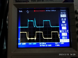
(These waveform are measured directly through the GPIO of C2000 device.)
--
Thanks & Regards,
Yale Li
