This thread has been locked.

If you have a related question, please click the "Ask a related question" button in the top right corner. The newly created question will be automatically linked to this question.

LAUNCHXL-F28379D: LAUNCHXL-F28379D

Part Number: LAUNCHXL-F28379D
Other Parts Discussed in Thread: C2000WARE

Hi ,

    I am bale to work with single ended adc in continuous mode for ADC B,C,D. But i want to use the ADC A as differential in continuous mode and i am not able to do it. i want tot use A2 and A3 as differential signal and A4 and A5 other differntial signal. It working in normal mode in while loop but i am unable to work it in continuous mode.

Please find my code for this and suggest me what to do. it is giving wrong data.

void Setup_AdcDifferentialContinuous()
{
uint16_t acqps;
acqps = 63; // 150ns


ADC_setPrescaler(ADCA_BASE, ADC_CLK_DIV_3_0);

//
// Set resolution and signal mode (see #defines above) and load
// corresponding trims.
//
ADC_setMode(ADCA_BASE,ADC_RESOLUTION_16BIT, ADC_MODE_DIFFERENTIAL);


// Set pulse positions to late
//
ADC_setInterruptPulseMode(ADCA_BASE, ADC_PULSE_END_OF_CONV);

//
// Power up the ADCs and then delay for 1 ms
//
ADC_enableConverter(ADCA_BASE);


TRACE_I(ADC_TRACE,"adc differential continuous mode config init \r\n");

ADC_setupSOC(ADCA_BASE, ADC_SOC_NUMBER0, ADC_TRIGGER_SW_ONLY,
ADC_CH_ADCIN2, acqps);
ADC_setupSOC(ADCA_BASE, ADC_SOC_NUMBER0, ADC_TRIGGER_SW_ONLY,
ADC_CH_ADCIN3, acqps);
ADC_setupSOC(ADCA_BASE, ADC_SOC_NUMBER1, ADC_TRIGGER_SW_ONLY,
ADC_CH_ADCIN4, acqps);
ADC_setupSOC(ADCA_BASE, ADC_SOC_NUMBER1, ADC_TRIGGER_SW_ONLY,
ADC_CH_ADCIN5, acqps);


ADC_setInterruptSOCTrigger(ADCA_BASE, ADC_SOC_NUMBER0,
ADC_INT_SOC_TRIGGER_ADCINT1);
ADC_setInterruptSOCTrigger(ADCA_BASE, ADC_SOC_NUMBER1,
ADC_INT_SOC_TRIGGER_ADCINT1);
//
// Disable Interrupt flags
//
ADC_disableInterrupt(ADCA_BASE, ADC_INT_NUMBER1);

//
// Enable continuous mode
//
ADC_enableContinuousMode(ADCA_BASE, ADC_INT_NUMBER1);
//
// Configure interrupt triggers
//
ADC_setInterruptSource(ADCA_BASE, ADC_INT_NUMBER1, ADC_SOC_NUMBER0);
//ADC_setInterruptSource(ADCA_BASE, ADC_INT_NUMBER1, ADC_SOC_NUMBER1);

ADC_enableInterrupt(ADCA_BASE, ADC_INT_NUMBER1);

// Clear interrupts
HWREGH(ADCA_BASE + ADC_O_INTFLGCLR) = 0x000F;


ADC_forceMultipleSOC(ADCA_BASE, ADC_FORCE_SOC0 | ADC_FORCE_SOC1);

}


  • Hello Vikas,

    Can you provide the input signals you are using? Have you verified whether these are sampled properly in single-ended mode? I will try to confirm the differential mode configuration setup for this device and get back to you tomorrow.

    Best regards,

    Omer Amir

  • Hello Vikas,

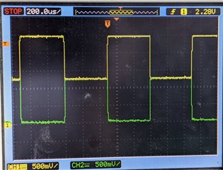
    Can you please clarify what you mean by the data is wrong? Are you getting any results? What voltage level are the results at? The input signals should look like the attached image. How are your inputs configured, can you provide schematics?

    Best regards,

    Omer Amir

  • Hi Omer ,

            I am working on the launch pad, I am not getting the data. on the pins, the data i should get approximate 42000 but getting 400 so its means its not working. can you please see my code and let me know whats wrong with this.

    Same code is made for single ended configuration its working on the ADCB.

  • these inputs are working properly in while loop  for differential adc with below configuration.

    void ADCA_differential_init(void)
    {
    EALLOW;
    AdcaRegs.ADCCTL2.bit.PRESCALE = 6; //set ADCCLK divider to /6
    AdcaRegs.ADCCTL2.bit.RESOLUTION = RESOLUTION_16BIT; //select resolution - 1 as 16bit for ADCA
    AdcaRegs.ADCCTL2.bit.SIGNALMODE = SIGNAL_DIFFERENTIAL; 

    AdcaRegs.ADCCTL1.bit.INTPULSEPOS = 1; //for ADCA

    AdcaRegs.ADCCTL1.bit.ADCPWDNZ = 1; //for ADCA

    DELAY_US(1000); //delay for 1ms to allow ADC time to power up

    EDIS;
    }

    void ADCA_differentialSetup_Software(void)
    {
    Uint16 acqps;

    acqps = 63; //320ns

    //ADCA
    EALLOW;
    AdcaRegs.ADCSOC0CTL.bit.CHSEL = 2; //SOC0 will convert pin A2 of adcA
    AdcaRegs.ADCSOC0CTL.bit.CHSEL = 3; //SOC1 will convert pin A3 of adcA
    AdcaRegs.ADCSOC0CTL.bit.ACQPS = acqps; //sample window is acqps + 1 SYSCLK cycles

    AdcaRegs.ADCSOC1CTL.bit.CHSEL = 4; //SOC0 will convert pin A4 of adcA
    AdcaRegs.ADCSOC1CTL.bit.CHSEL = 5; //SOC1 will convert pin A5 of adcA
    AdcaRegs.ADCSOC1CTL.bit.ACQPS = acqps; //sample window is acqps + 1 SYSCLK cycles
    }

    In main I am calling.

    //ADCA_differential_init();

    //ADCA_differentialSetup_Software();

    while(1)

    {

           AdcaRegs.ADCSOCFRC1.all = 0x0003; //SOC0 and SOC1 = 1; //for ADCA

          adc_result1 = AdcaResultRegs.ADCRESULT0;

          adc_result2 = AdcaResultRegs.ADCRESULT1;

    }

  • Hello Vikas,

    the data i should get approximate 42000 but getting 400

    Can you please provide a scope of both inputs for this differential input? They should be 180 degrees out of phase.

    Regarding your code above, I see you're not using any sort of ADC interrupt. Is there a reason you're not at least polling the flag for when the conversion ends? You're reading the result immediately after triggering the SOC, which is not guaranteed to have a result ready.

    Best regards,

    Omer Amir

  • I want to use the interrupt and trying to use the differential ADC in continuous mode. so above code i am using but its not working.

    The positive pin A2 value is greater than A3 what we are giving. like A2 we are giving 2 v and A3 is having 1.5 volt so we should get the value for 0.5 volt in digital.  that should be 32767+ (65535/6 * 0.5). 

    kindly help why above program is not working.

  • i did not find much about the differential adc in continuous mode, Can you please provide any application code of differential adc in continuous mode.

  • Hello Vikas,

    I want to use the interrupt and trying to use the differential ADC in continuous mode

    I see you configuring the interrupt and continuous mode, but there are two issues: 1) lines 39-42 are overwriting the interrupt configuration, so I'm not sure which SOC is supposed to trigger interrupt 1, and 2) when you read the results you aren't checking the proper flag for the interrupt, so the configuration isn't doing anything.

    The positive pin A2 value is greater than A3 what we are giving. like A2 we are giving 2 v and A3 is having 1.5 volt so we should get the value for 0.5 volt in digital.  that should be 32767+ (65535/6 * 0.5). 

    Can you please provide a screenshot or picture of an oscilloscope reading of this?

    Best regards,

    Omer Amir

  • Hello Vikas,

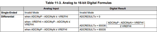
    You should be calculating the voltage from the results using the below table:

    It seems like the way you're configuring the inputs, they will always be offset by about 1.2V. If this is expected, then that's fine.

    Regarding reading the result 400 when you're expecting 42000 try to poll the proper interrupt flag to wait for the result to actually be ready before reading the register. Make sure that the 2 inputs are not connected to anything that is loading any of the pins and, try using single-ended mode on both these channels to see if the results you are getting there are as expected. Try these things and let me know how it goes.

    Best regards,

    Omer Amir

  • Part Number: LAUNCHXL-F28379D

    I working on the differential adc continuous mode, i want to check how fast the ADCINT1 interrupt is generating for the ADC , how can i make any isr for this interrupt , which macro should i choose for the vector table for this interrupt.

  • how can i check , how fast the ADCINT1 interrupt is triggering and how fast my adc is working, which macro should i used for this interrupt from the vector table.

  • Hello Vikas,

    Please do not create duplicate threads for questions that are the same, this only creates more difficulty in addressing the question.

    If you want to use an ISR for the ADC you can import an example and see how they are typically set up, as it can outline in better detail what you need to do to set up the ISR and interrupts. One example can be found at C2000Ware_4_XX_XX_XX\driverlib\f2837xd\examples\cpu1\adc. You can look at the adc_ex5_soc_continuous example for using the continuous mode on the ADC. Let me know if you have further questions about this.

    Best regards,

    Omer Amir