This thread has been locked.

If you have a related question, please click the "Ask a related question" button in the top right corner. The newly created question will be automatically linked to this question.

TMS320F280025: SCI communications byte timing

Part Number: TMS320F280025
Other Parts Discussed in Thread: SYSCONFIG, C2000WARE

I am using the SCI in an interrupt mode. No FIFO.

When I receive a charachter (8 bits, 9600 baud, no parity, one stop bit) I get an interrupt. In the interrupt routine, I pull the character out of the buffer and put it in my own RXBuf buidling the message. All the while, I look for a <CR> as the termination character so I can set a flag that tells the main routine that there is a message ready. This is a technique I have used for 40 years or so across a wide variety of processors. Those include the 2406 and 28069. Really basic stuff.

If I use a terminal program like Hyper terminal and send my messages one character at a time, all is well. The bytes get put in to my receive buffer, When I hit <CR> the message is decoded and acted upon.

PROBLEM:

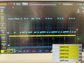
If I use my application (been using it for 20 plus years) which allows me to send the entire message with one click, the interrupts still happen on every charater, but what comes out of the 280025 RXBUF is gibberish. The bytes comeing out do not match what is going in. IT's as though the characters have not actually been fully shifted in to the buffer. Naturally, the bytes coming out of my application come one right after the other but the proper start and stop bits are there so it should NOT be a timing thing.

Any clue as to what the heck is going on?

As always, all brilliant suggestions and dumb ideas welcome...

  • Hi David,


    Thanks for your questions and succinct explanation, much appreciated. So with SCI module there's actually a few things that could be causing this (it's admittedly a bit more "tricky" than other UART peripherals due to some atypical behavior, something we hope to remedy in future devices).


    1. First thing to keep in mind that is possibly causing this:

    The Buffer interrupts (any SCI interrupts really) require effectively 2 stop bits between interrupts. Explanation:

    Every time an interrupt fires on the SCI, the interrupt won't start until 7/8th of a stop bit of detection time. Exact numbers are: delay between interrupt trigger (end of stop bit) and ISR actually starting == ((7*BAUD_CLK_PERIOD)/8+3*SYSCLK_PERIOD). This means that the interrupt only has 1/8th of a bit period to execute. At 9600 baud rate this is probably okay, unless the ISR itself is really long.

    This is an issue in the SCI itself. So a total of about 7/8 bit period detection time of is needed between interrupts. This is NOT typical of most other device UARTs and is the most common cause for gibberish in C2000 devices when all the normal stuff (baud rate mismatches, noise, etc.) have been accounted for. Yes this is not ideal, because it requires the other device (PC in this case) to insert delays between bytes. If there IS sufficient delay between bytes (manually clicking by a user sounds like there SHOULD be enough delay) then the next possible issue could be the cause. Also it sounds like you've used this with other "SCI" modules on C200 devices like 28069 so this may not be the cause either.


    2. Another possibility is the baud rate mismatch. I'm pretty sure you probably have this set properly, and at low baud rates like 9600 there's plenty of granularity. But if LSPCLK on 280025 is set really low, then this COULD be an issue. This falls more into the "dumb ideas" category, but it's still worth a sanity check Slight smile


    3. Maybe a software thing? Have you by chance set Sysconfig -AND- driverlib functions for config? My worry would be accidentally setting the config using Sysconfig after manually writing using driverlib. Most of the new C2000Ware packages have Sysconfig files in the examples by default so if you recently started a new project based on another project, there may be Sysconfig set in there.


    One of the above may be the issue root cause, but maybe not. Could you send a scope capture of the data coming in to the RX pins of the device just for me to sanity check? It's probably not a physical thing, but it's always worth a check on that.


    Regards,

    Vince

  • Thanks for the reply. 

    Here are two scope shots. Cyan trace is the data. Yellow goes low shortly after the receive interrupt is entered (you can see that in the code I included). It goes high just before the receive interrupt is exited. IT's just a little "blip" so you can see that the interrupt is very short.

    I also show the memory contents of the buffer in the lower right corner.


    That message is "/111<CR>". The data in the buffer should be three 0x41 and one 0x0D.

    INterestingly enough, here is /1UUU<CR>. I chose a bit pattern to get a 010101.... type pattern going on. In this case, the buffer data is correct. 

    It appears that the data is being shifted. Is it possible that the data has not actually made it to the hardware RX buffer when the interrupt fires? Perhaps the silicon designers glossed over this case assuming that people would only use FIFO type comms?

    //receive interrupt
    __interrupt void SCIRXINTA_ISR(void)
    {
    asm(" CLRC INTM"); /* enable global interrupts */
    // PieCtrlRegs.PIEACK.all|=0x100; // Issue PIE ack
    
    if(boolComLEDStatus == 0)//if LED is on
    {
    boolComLEDStatus = 1;//LED
    GPIO_writePin(DEVICE_GPIO_PIN_COMM_LED, 0);//turn ON COMM status LED <<<<<--------yellow trace goes low
    LEDComCounter = LEDComRate;
    }
    // asm(" CLRC INTM"); /* enable global interrupts */
    if(SCI_isDataAvailableNonFIFO)
    {
    
    if (RXState != OEMCheckSum)
    // SER_IN = SciaRegs.SCIRXBUF.all & 0x7F;
    SER_IN = SCI_readCharNonBlocking(SCIA_BASE);
    else
    // SER_IN = SciaRegs.SCIRXBUF.all;
    SER_IN = SCI_readCharNonBlocking(SCIA_BASE);
    }
    else
    {
    return;
    }
    if (!CommunicationsFlags.xmiting)
    {
    Interrupt_clearACKGroup(INTERRUPT_ACK_GROUP9);
    switch (RXState)
    {
    case 0: //we're looking for the very first start character after
    //we\\'ve been reset. We'll also set the unit address from here.
    {
    
    if (SER_IN == '/')
    {
    RXState = DTAddress;
    RCV_PNT = 0;
    }
    else if (SER_IN == STX)
    {
    RXState = OEMAddress;
    RCV_PNT = 0;
    RXSum = STX;
    }
    // SCI_clearInterruptStatus(SCIA_BASE,SCI_INT_RXRDY_BRKDT);//clear rx int flag
    // SciaRegs.SCIFFTX.bit.TXFFINTCLR=1; // Clear SCI Interrupt flag
    // PieCtrlRegs.PIEACK.all|=0x100; // Issue PIE ACK
    break;
    
    }
    
    //===================================
    //DT PROTOCOL
    
    case DTStart:
    {
    if (SER_IN == '/')
    {
    RXState = DTAddress;
    RCV_PNT = 0;
    // for (xser=0;xser<5;xser++)//prevent running old commands
    // {
    // RCV_BUF[xser] = 0xFF;
    // }
    
    }
    break;
    }
    
    case DTAddress:
    {
    ADDRESS = SER_IN;
    if (ADDRESS == '/')
    {
    RXState = DTAddress;
    RCV_PNT = 0;
    // for (xser=0;xser<5;xser++)//prevent running old commands
    // {
    // RCV_BUF[xser] = 0xFF;
    // }
    
    }
    else
    {
    //set the receive state to look for the <CR>
    //, address decoding will be done in the command decode section
    // if (ADDRESS == UnitAddress)
    RXState = DTCR;
    // else
    // RXState = DTStart;
    }
    break;
    }
    case DTCR:
    {
    
    if (SER_IN == '/')
    {
    RXState = DTAddress;
    RCV_PNT = 0;
    
    }
    else if (SER_IN == STX)
    {
    RXState = OEMAddress;
    RCV_PNT = 0;
    RXSum = SER_IN;
    }
    else if (SER_IN == cstBackSpace)
    {
    if (RCV_PNT != 0)
    RCV_PNT --;
    }
    else
    {
    RCV_BUF[RCV_PNT] = SER_IN;
    if (SER_IN == 0x0D)
    {
    CommunicationsFlags.DTProtocol = 1;
    CommunicationsFlags.OEMProtocol = 0;
    CommunicationsFlags.MSG_Here = 1;
    RXState = 0;//wait for either start character
    }
    RCV_PNT ++;
    if (RCV_PNT > cstRXBufLength -1)
    {
    ErrorCode = cstCommandOverFlow;
    RCV_PNT--;
    
    }
    }//end else
    break;
    }//end case


    //=====================================
    // OEM PROTOCOL
    case OEMStart: //wait for start of transmition
    {
    if (SER_IN == STX)
    {
    RXState = OEMAddress;
    RCV_PNT = 0;
    RXSum = SER_IN;
    }
    else if (SER_IN == '/')
    {
    RXState = DTAddress;
    RCV_PNT = 0;
    }
    break;
    }
    
    case OEMAddress: //wait for address
    {
    ADDRESS = SER_IN;
    RXSum = RXSum ^ SER_IN;
    if (ADDRESS == STX)
    {
    RXState = OEMAddress;
    RCV_PNT = 0;
    RXSum = SER_IN;
    }
    else if (SER_IN == '/')
    {
    RXState = DTAddress;
    RCV_PNT = 0;
    }
    else
    {
    //set the receive state to look for the sequence byte
    //, address decoding will be done in the command decode section
    // if (ADDRESS == UnitAddress)
    RXState = OEMSequence;
    // else
    // RXState = 0;//wait for either start character
    }
    break;
    }
    
    case OEMSequence: //wait for sequence number
    {
    Sequence = SER_IN;
    RXSum = RXSum ^ SER_IN;
    
    if (Sequence == STX)
    {
    RXState = OEMAddress;
    RCV_PNT = 0;
    RXSum = SER_IN;
    }
    else
    {
    RXState = OEMETX;
    }
    break;
    }
    
    
    case OEMETX: //receive characters until ETX
    {
    RXSum = RXSum ^ SER_IN;//xor
    
    if (SER_IN == STX)
    {
    RXState = OEMAddress;
    RCV_PNT = 0;
    RXSum = SER_IN;
    }
    else if (SER_IN == '/')
    {
    RXState = DTAddress;
    RCV_PNT = 0;
    
    }
    else
    {
    RCV_BUF[RCV_PNT] = SER_IN;
    if (SER_IN == ETX)
    {
    RXState = OEMCheckSum;
    }
    RCV_PNT ++;
    if (RCV_PNT > cstRXBufLength -1)
    {
    ErrorCode = cstCommandOverFlow;
    RCV_PNT--;
    
    }
    }//end else
    break;
    }//end case
    
    case OEMCheckSum: //wait for checksum
    {
    if (RXSum == SER_IN)
    {
    
    CommunicationsFlags.MSG_Here = 1;
    CommunicationsFlags.DTProtocol = 0; //set the protocol
    CommunicationsFlags.OEMProtocol = 1;
    }
    RXState = 0;//wait for either start
    break;
    }
    default:
    {
    ErrorCode = cstCommunicationsError;
    }
    }//end switch
    // RI = 0;
    SCI_clearInterruptStatus(SCIA_BASE,SCI_INT_RXRDY_BRKDT);//clear rx int flag
    GPIO_writePin(DEVICE_GPIO_PIN_COMM_LED, 1);//turn OFF COMM status LED Debug stuff<<<<<<-----Yellow Trace goes high
    boolComLEDStatus = 0;//LED
    }
    else
    {
    ErrorCode = ErrorCode;
    }
    // RI = 0;
    // LED2 = 1;
    
    
    // PieCtrlRegs.PIEACK.all|=0x100; // Issue PIE ack
    // GpioDataRegs.GPACLEAR.bit.GPIO24 = 1;
    return;
    } //end receive interrupt

  • Typo in previous message. The "111" should, of course, be 0x31 etc...

  • Hi David,


    This definitely looks like the issue I mentioned in #1 above. These are back-to-back bytes received in your image (only 1 stop bit), and each interrupt ISR MAY take longer than 1/8 bit period, given how long the ISR appears to be.

    I recommend to move most of the code outside of the ISR so that the ISR is ONLY moving the data into normal memory, and so the next interrupt can be triggered while the previous one is being processed in the main (without blocking the next one's move).

    Regards,

    Vince

  • What is different about this UART that causes that?

    Please look at the photo again. The yellow goes low when the interrupt routine starts, it goes high when the interrupt routine exits. It completes the entire routine before the next start bit. 

    From the time I was using 8080's, 8031's Z80's 2406, 28069 etc, (yes, I'm old) the UARTS were double buffered, That is, the incoming bit stream would enter the shift register, when th stop bit was detected, the entire byte got placed in to the RXBuf and the interrupt was triggered. As long as the byte was extracted from the RXBuf register before the next entire byte was shifted in to the RXshift register, you were fine. That allowed you to take a millisecond  (at 9600 baud)  to get your byte and frankly mess around for a loooooong time without losing data. 

    Also, the data I see is not actually "giberish", it has the look of the bit pattern I sent only shifted about 4 bits right from where it is supposed to be.

    So someone decided it was a great idea to break something that has worked so well for several decades? That really leaves me scratching my head.

  • Hi David,

    [edit, it sent before completing sentence]

    Apologies, I had thought you had left it out of the scope capture, the resolution got reduced a lot and made it look like noise Slight smile

    And if this really is the same program that you were using previously on other devices then it should behave identical to 28069 (with only change being 16-level FIFO). Is the hardware communicating to F280025x identical as the hardware that communicated to F28069? If so, somethings different on the F280025x hardware provided. The issue is I can't see anything directly wrong with the data itself.

    Does the device handle non-interrupt code properly? Meaning, if you poll, does it work correctly?

    Regards,

    Vince

  • Hi Vince, 

    I do not use the FIFO since I qualify each character as it comes in. And yes, this is essentially the code I wrote for an 8031 8 bit micro in 1983. I've been using what is essentially the same thing across time and a dozen different models of micro processorsince then. Three of those were different TI DSP's. Only thing changed is the actual method of accesing the hardware. 

    Just for grins, I did set the stop bits to 2 and "voila" it works. I really do not like doing that since ALL our stuff defaults to 9600,N,8,1...

    What that tells me though is there is indeed something different in the 280025 and that doing an imediate read of the RXBUF when coming in to the interrupt gets out data that has not fully been shifted in to place. Even though the diagram shows that the data path between the input shift register and the RXBUF register is paralell, is it really?

    I am pondering doing another test where I just put in a :waste some time" for loop before reading the RXBUF and see what that does. 

    If you have any other great ideas, please do share.

    Best Regards,

    David

  • Hi David,

    Glad that the 2 stop bits works, but I understand the dislike for this (this is a severe limitation in the interrupt scheme, and you can bet we have raised this concern to be re-designed for next generation devices). Specifically because we know that most devices do not default to 2 stop bits, like you rightly mentioned.

    Just to give you some reasoning on WHY it's happening: essentially the detection mechanism for an interrupt is what is the bottleneck here. The data's in the shift register and buffer like expected. It's just the INTERRUPT is not triggering until it is "100% certain" it's a stop bit that it's received, and that requires a full ~7/8th bit time. Which at 9600 baud rate should be fine for most ISR lengths. But sometimes it isn't.


    Now here's one additional workaround that works, if you can spare the CPU cycles for it: if you do polling (so disable interrupts completely and just read the status bits of SCI to see if anything arrived), this issue is non existent. Basically, the status bits for data received get set before the actual interrupt fires. So you can avoid missed/misaligned data by doing polling. But obviously, this won't work in every application, and is CPU intensive.


    Thanks for debug on this, let me know if any other questions on this.

    Regards,

    Vince

  • Hi Vince, 

    I'm still not understanding the explaination in regards to what I see. If the interrupt does not fire until the data is certain to be in the RXBUF register, then when I enter my service routine and grab that data from the register, it should be correct. 

    However, after a bit more testing, it seems that the serial data is being shifted directly in to the RXBUF register. Originally I thought that the data had not been fully loaded in to the RXBUF register. I added a "for" loop to waste time in the ISR (interrupt service routine) prior to reading the character. This only changed the pattern of bits in the register. 

    I also did a test where I left the UART settings in the 280025 at 1 stop bit but changed the transmitter to 2 stop bits. This works. From these two tests, it appears that there is no "double buffering" of data at all. 

    I did see in the data sheet it claims that the serial data is "buffered". I also se something that looks like there was an 8 deep buffer configuration but I am not sure if that is related to the "LIN" type serial hardware. 

    Is there nothing other than transmitting 2 stop bits that you can think of that will allow this processor to work? I'm trying to replace the 2406 (which are VERY hard to come by thyese days) with this processor, but the application has to be "drop in compatible"...

    Also, while I have your attention, in previous versiojn of code, I never used "API"" I used direct reference of hardware like:

    SciaRegs.SCIHBAUD =0x0001; // 9600 baud @LSPCLK = 20MHz (80 MHz SYSCLK).
    SciaRegs.SCILBAUD =0x0003;

    When I atempt that in my current project, I get errors. Any way to easily make that happen? I'm NOT a compiler expert by any means...

    David

  • Hi David,

    I'm still not understanding the explaination in regards to what I see. If the interrupt does not fire until the data is certain to be in the RXBUF register, then when I enter my service routine and grab that data from the register, it should be correct. 

    If I'm understanding what you're seeing, then to explain what I'm meaning: The issue is that the delay before starting the ISR causes the next byte (not the first byte) and subsequent bytes to be shifted because it doesn't re-start RX polling until too late. So it's like the RX starts looking at the next byte halfway through its start bit. And then the next byte after that it's now not starting within the start bit. It starts reading it within the first data bit. And then you can get errors on top of that too.

    Is there nothing other than transmitting 2 stop bits that you can think of that will allow this processor to work?

    The other workaround I mentioned previously could work, but may not be acceptable to your project, it depends on the system:

    Now here's one additional workaround that works, if you can spare the CPU cycles for it: if you do polling (so disable interrupts completely and just read the status bits of SCI to see if anything arrived), this issue is non existent. Basically, the status bits for data received get set before the actual interrupt fires. So you can avoid missed/misaligned data by doing polling. But obviously, this won't work in every application, and is CPU intensive.


    To answer the next question:

    Also, while I have your attention, in previous versiojn of code, I never used "API"" I used direct reference of hardware like:

    SciaRegs.SCIHBAUD =0x0001; // 9600 baud @LSPCLK = 20MHz (80 MHz SYSCLK).
    SciaRegs.SCILBAUD =0x0003;

    When I atempt that in my current project, I get errors. Any way to easily make that happen?

    Yes, two ways:

    If you would like to continue to use driverlib (recommended because many of the API calls can be pretty useful) then you can do direct read/writes to the given registers using the hw_memmap.h and hw_sci.h files.

    So you get the SciaRegs equivalent in hw_memmap.h (SCIA_BASE). This is the base address of the SCIA registers

    And you get the SCIHBAUD equivalent in hw_sci.h (SCI_O_HBAUD). This is the offset of the HBAUD register within the SCI registers space.

    And then you can put it together with:

    HWREGH(SCIA_BASE + SCI_O_HBAUD) = 0x0001; // or some value you want to write


    [EDIT: forgot to put the second way, see below]

    Second way is to use the "device_support" folder in C2000Ware (instead of "driverlib" folder) as your code base. "device_support" folder is all direct register reads/writes. We don't recommend this for many reasons, one being that it can be much harder to write code originally, and to debug later.

    Regards,

    Vince

    Regards,

    Vince

  • HI Vince, 

    I appreciate the discorse but the explanation of the interrupt generation being the root cause because it needs to be "certian" still does not make sense as to why the data in the RXBUF is messed up.

    When the interrupt fires (regarless of how long it takes) data is prevented from being transfered from the RX shift register to the RXBUF because the RXENA is disabled by the CPU until the ISR consumes the data. 

    If no one comes along to get the data from the RXBUF, the shift register will keep shifting in data until the next stop bit in which case, an "overrun" error would be generated letting the guy writing the code know that he missd a byte. 

    So, that is the only issue with ISR length. As long as the ISR length is less than the time it takes to shift in the next character, all is well.At least it has been for the last 40 years or so... 

    My little PacMan UART video shows that even PACMAN (My RXISR) takes a little time to consume the data from the RXBUF while the databits are still being shifted in, but still there should be no reason for data corruption.

    Also, if ISR response time were the root cause, then enabling the FIFO should also take care of the issue. In that case, as long as your message was less than 16 bytes, by the time you got around to reading the message, everything should be great. Here again, I tried enabling the FIFO and the data is corrupted the same as without the FIFO. 

    Regards,

    David

  • Hi David,

    [EDIT: corrected image to show 7/8 stop bit issue, was incorrectly showing 6/8th stop bit]

    Thanks for this reply, the pacman animation was a very nice touch Smile

    So you are 100% correct on this following statement, assuming that the RX begins to read the bytes normally at the right time:

    My little PacMan UART video shows that even PACMAN (My RXISR) takes a little time to consume the data from the RXBUF while the databits are still being shifted in, but still there should be no reason for data corruption.

    This is correct. Assuming that the SCI module started reading the data again normally, everything in the RXBUF should not have any corrupted data.


    Now I have a question regarding this comment you mentioned, which will lead to one of two answers depending on your response:

    Here again, I tried enabling the FIFO and the data is corrupted the same as without the FIFO. 


    Question: Does the data corruption happen at the END of the very first set of 16-bytes (right after the FIFO interrupt occurs)? Let me know which of the two below is correct:


    Answer #1: No, the data gets corrupted in the middle of the FIFO, within the first 16 bytes of data sent to the SCI after initialization.

    Root Cause #1: If this is the case, and you are certain that right after initialization, within the first 16 bytes that data corruption occurs (before the VERY FIRST FIFO interrupt triggers), then this is something I have not seen before. We need to debug this differently than we're currently doing. It could be something related to not clearing the SCI fully during initialization. But I don't think this is it.


    Answer #2: Yes, the data corruption happens immediately after the first FIFO interrupt (or one of the subsequent FIFO interrupts).

    Root Cause #2: See image below, hopefully this illustrates what the issue is. Basically, the ISR can cause the SCI strobes to get shifted by 1 every interrupt. This leads the DETECTION of what bit we are looking at to eventually get skewed. Eventually in one of the bytes, the SCI module will think data bit #1 is the start bit. And it thinks data bit #2 is data bit #1. Which it will happily shift into the RXBUF. So the data is corrupted.

    Regards,

    Vince

  • Door #2...

    It would seem that there is something unique about this UART in the 280025 that is different than previous incarnations of UARTS in the history of UARTS. 

    I can see the loss of syncronization after about the 3rd or 4th byte. You can see the yellow trace, the first low going pulse happens  THis test is "NON FIFO", but that does not matter. IT fits the description you gave to a "T".

    So, the BIG QUESTION!!

    How to fix/work around it. I have 5000 of these chips slated for a product redesign of our flagship product that uses the 2406. If I can't talk to the board, these chips are just so much silicon scrap.

    What exactly is the hardware looking for to allow the re-syncronization of the data?

    Is there a flag I can clear imediately in the ISR that will allow the proper sync to the next start bit?

    Is this only related to interrupts on the SCI? If I (begrudginly) figure a way to handle the reception of data by just polling the RXRDY bit, and assuming I do it often enough, does this sync problem go away? 


    More questions related to this. is the entire Interrupt structure possibly victim to this? Will the CAN interface show the same issue? SPI? I2C?

    All of my various communications techniques are interrupt driven and this bug will kill the ability of my product to function.

    Does your UART designer understand the root cause and how to fix it?

    If so, when is that fix going in to the chip design? That is the Really big question...

    David

    P.S., I'm glad you liked the PACMAN GIF...

  • Dave,

    Vince is out for a few days, apologies if this is covered in the above, but can you advise which GPIOs you are using for the SCI on the F28002x device?  Can you try to change the synchronization to ASYNC mode on all of the pins you are using(GPyQSEL# control register).  Since SCI will be synchronizing to its local clock I want to make sure we are not also sync'ing the signal to CPU clock as well.

    Fundamentally there is no change from F28069 device that is working to the F28002x device wrt SCI.

    Best,

    Matthew

  • Hello Matthew, 

    I am using GPIO 28 pin 4 for the SCIA RX. 

    Normally, I would pop open the "view registers" to look at the setting you are talking about. However, for some reason, my "registers" window no longer show up in CCS12. I probably hit some hidden button somewhere and can not get it back...Any ideas on that?

    David

  • Hi David,

     [EDIT: clarified the interrupt comments and added interrupt nesting link]

    Thanks for the follow-up and confirmation on this, very much appreciated. I'll directly answer this as fully/succinctly as possible (as I'm going to be out of office starting today and returning next Monday, so please expect delayed response until that time).

    For what is happening in the hardware:

    Is this only related to interrupts on the SCI? If I (begrudginly) figure a way to handle the reception of data by just polling the RXRDY bit, and assuming I do it often enough, does this sync problem go away? 

    Possible re-synch blocker #1: I can sanity check this with the designers, but I believe (not certain) that the hardware waits for the SCI internal interrupt flags to be cleared, specifically the RX-related interrupt flags in this case. Can test this by doing an immediate read + SW reset in the ISR or (if using FIFO) RXFFINTCLR instead of SW reset.

    Possible re-synch blocker #2: But what I need to double check is whether SCI is looking at the PIE interrupts (unlikely but possible) and waiting for that to be cleared. If that's the case, we could maybe implement some software interrupt nesting to get around this. Not ideal, but technically could help with this if that's the case. Here is a link to interrupt nesting in case you'd like to give it a try offline, I can provide assistance with this too: https://software-dl.ti.com/C2000/docs/c28x_interrupt_nesting/html/index.html


    Now the question regarding polling:

    Is this only related to interrupts on the SCI? If I (begrudginly) figure a way to handle the reception of data by just polling the RXRDY bit, and assuming I do it often enough, does this sync problem go away? 

    Yes this is ONLY related to the interrupts of SCI. This will go away if you do polling, which we've tested to work. Very much not ideal at all, for many reasons. But it works.


    Now the question about other interfaces and the full interrupt structure:

    is the entire Interrupt structure possibly victim to this? Will the CAN interface show the same issue? SPI? I2C?

    All of my various communications techniques are interrupt driven and this bug will kill the ability of my product to function.

    No, this is a limitation in the SCI only. Interrupts in other communications will not have this issue.

    I am looking into this, but I think the change that was made between SCI in 2806x and 28005x to increase the SCI FIFO size also did something to the SCI's internal interrupt architecture unintentionally. The PIE scheme is unrelated to this.


    Does your UART designer understand the root cause and how to fix it?

    If so, when is that fix going in to the chip design? That is the Really big question...

    The designers are aware, and update requests have been filed.

    Existing device families with SCI will not get any fixes applied.

    One note is that the LIN peripheral in SCI mode (which is also capable of UART communications) is not expected to have this issue as it is based on a different design.


    Let me know if any questions on this, and I'll get back to you on Monday! Other TI experts may be able to assist with related other questions in the meantime. Thanks for your patience!

    Regards,

    Vince

  • Hi Matthew, I got the register view up again. I loaded my code and manually changed the input qualification type for GPIO28 to "11" = ASYNC. This was to no avail since my serial data is still correpted and I can see by the response of my test bits in the COMRX routine that after a few bytes of data, the interrupt happens later and later. Pretty sure it has the behaviour that Vince described in scenario 2 above. Something in the input "start/stop bit" detection is getting thrown off.

    As mentioned, this is essentially the same code I've been using for decades. Just a tweak here and there for the different nomenclature of the hardware registers involved. 

    I am doing this development on one of your 280025 control cards plugged in to a docking station. 

    If you can show me a receive interrupt service routine that works 100% of the time even if it takes up to half way through the next byte to get there, I will happily use that. 

    Regards,

    David

  • Hi Vince, 

    So, much as I did not want to do this, I tagged a look at the RXStatus at the end of my 20kHz timer loop. If that says a character is ready, I call my old RX routine (after removing all things interrupt related) and handle things as usual. I also left the TX interrupt alone. Long and short of it, communications are now good up to 115200 baud which is good enough for now.

    I hope you guys fix this error in the UART because it really should NOT behave this way.

    Till next time...

    David

  • Hi David,

    Thanks for the follow-up and apologies on this issue in the SCI module. This is definitely something we have requested fixes for in future devices, as it's obviously more than just a minor inconvenience. I am glad you were able to use a workaround, but again, we are looking into correcting this in future revisions of the peripheral. We may instead use the LIN-SCI and newer HS-UART peripheral to replace this older SCI peripheral. But this will be for future devices.

    Regards,

    Vince