This thread has been locked.

If you have a related question, please click the "Ask a related question" button in the top right corner. The newly created question will be automatically linked to this question.

TMS320F28034: Failure of programming F28034

Part Number: TMS320F28034
Other Parts Discussed in Thread: UNIFLASH

Hi Expert,

My customer are using F28034 for mass production, there have some possibility that fail to program the F28034 by JTAG, the error report Verification failed, 

actually they need to program APP code and Boot code independently, the error only occur when they program Boot code

They program the APP code firstly and always successfully, then program Boot code, some possibility will fail. 

It is not allowed to program Boot code first and then APP because there have one flash sector are shared by both Boot code and APP code, 

They use a .bat file to run command which will run Uniflash to program APP code and bootloader code automatically.


They monitor the waveform below when do programming, have a little drop but seem still at normal range. 

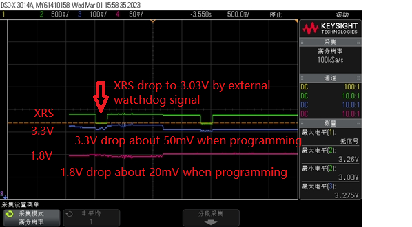
The issue may also related to hardware of external watchdog circuit,  when XRS pin is connected to external watchdog, there have a little voltage drop to about 3V as above showed, in this case, there will have possibility fail to program Boot code, but always successfully program APP code at the first time. 

if they disconnect XRS pin to external watchdog and keep XRS pin stable, then always program both Boot code and APP code successfully.

Any suggestion on how to fix this issue?  I will update schematic by email when get customer's schematic. 

  • Strong,

    Is the issue that the flash takes too long to program, causing the external WD to time out and pull XRSn low?

    It certainly does seem that the external XRSn signal is doing something to the C2000, even though it has not dropped low enough to be considered a logical "low".

    Its hard to tell from the scope plot, can you confirm the time the XRSn signal has the low going pulse.  I think it might be 250ms, but want to be sure.  My point here is that I don't think this is our device driving XRSn due to any voltage threshold break, its active low is much shorted, ~800us if my memory is correct.  I think this is backed up by customer observation as well.

    Is this the first program of the device from the factory?  If so, customer can save some time by not calling erase function from Uniflash, and just calling programming.  If timeout is the issue, this will save alot of time to not erase the device(since it comes from TI already erased).

    Best,

    Matthew

  • Matthew,

    Is the issue that the flash takes too long to program, causing the external WD to time out and pull XRSn low?

    --> NO, external WD will time out and have output, but there have other circuit to keep XRS always high when connected JTAG, I send you the schematic by email for details. 

    It certainly does seem that the external XRSn signal is doing something to the C2000, even though it has not dropped low enough to be considered a logical "low".

    Its hard to tell from the scope plot, can you confirm the time the XRSn signal has the low going pulse.  I think it might be 250ms, but want to be sure.  My point here is that I don't think this is our device driving XRSn due to any voltage threshold break, its active low is much shorted, ~800us if my memory is correct.  I think this is backed up by customer observation as well.

    --> 250ms low pulse is influenced by external watchdog output, but the low pulse voltage still have about 3V, which should be high level. 

    Is this the first program of the device from the factory?  If so, customer can save some time by not calling erase function from Uniflash, and just calling programming.  If timeout is the issue, this will save alot of time to not erase the device(since it comes from TI already erased).

    --> it seem for first time to program APP code, always ok, then the code will run from APP, APP code will control a LED to show if APP code run normally, 

    if LED showed ok, then will be able to program boot code,

    if not, then will fail to program boot code. 

    but what strange is that if they remove external circuit, then always to program both APP and boot code well. 

  • Strong,

    I believe I found the PN for the watchdog IC, or at least something similar from STM, it has the same pins as well as the same time for driving XRSn low ~250ms.

    At any rate, when the flash begins programming/erasing there is going to be some instantaneous current demand in addition to the nominal current.  If there is a lack of bulk decap near the C2000 pins, this can cause issues if we droop too low. 

    However, in this case, we are not seeing the C2000 have an issue, but it seems that this droop is enough to trigger the external WD, even if it doesn't appear to go low enough to actually trigger reset for the C2000 MCU.

    I'm not sure if customer has some local decap near the supervisor, or the actual placement of the supervisor on the PCB relative to the C2000 so that it is "seeing" the same voltage the C2000 is seeing.  Essentially we need to try and prevent this"false" low driven signal from the watchdog supervisor.

    Another thing I noticed is the 120Ohm series resistor between RST and the XRSn of the C2000.  Because XRSn from C2000 is bi-directional it needs to be able to drive this as well as receive.  The note in the STM DS I found suggested a 4.7kOhm resistor vs what I see in the schematic of 120Ohm.  I'm not sure this is related, but I would try to change this resistor value to the 4.7kOhm to see if anything changes.

    Best,
    Matthew

  • Matthew,

    customer change the resistor value to 4.7kOhm,  but still have this issue.

    as mention above, for the first time to program APP code, then everything is ok, 

    run APP code automatedly as they use Uniflash, if APP run ok, then it is able to program Boot code,

    If APP code run to illegal ISR for unknown reason, then fail to program Boot code.

    in this case, if customer disconnect Emulator and connect again, then is also ok to program Boot code. 

    if watchdog and reset circuit are removed, then everything is ok.

    so the conclusion maybe:

    watchdog and reset circuit will affect the APP code and lead to illegal ISR, when illegal ISR occur, 

    this may affect the emulator not able to reset the MCU? 

    I don't have idea how to help fix the issue as external watchdog circuit is must have for them, below suggestion is hard to convince customer as the voltage drop about 10% and still have about 3V, any other suggestion for customer?  

    Essentially we need to try and prevent this"false" low driven signal from the watchdog supervisor.

  • Can customer try to overdrive the watchdog power detect pin externally to see if we can eliminate the pulse on XRSn?  I'd like to see if we get rid of that if things work OK.  Meaning we need more decap physically local to the Watchdog IC so it does not see this small droop caused by flash programming and issue reset.

    Best,

    Matthew

  • Matthew,

    Could you clarify how to overdrive the watchdog power detect pin externally? sorry I don't quite understand. 

  • do you mean give a external pulse on WDI pin?

  • Strong,

    Yes, once the device is powered correctly, from external power supply or circuit drive that node to 3.3V.

    Alternatively, they could lift the WD RST signal pin on that IC, and then scope that signal during flashing to see the unloaded behavior of the WD IC.  That would tell us if it is driving a full XRSn low and the PCB circuit is runting it, or it is not driving XRSn fully.  With pin lifted the C2000 shouldn't have any negative effects either.

    Best,

    Matthew