This thread has been locked.

If you have a related question, please click the "Ask a related question" button in the top right corner. The newly created question will be automatically linked to this question.

TMS320F280049C: ePWM Interrupt Latency is very high.

Part Number: TMS320F280049C
Other Parts Discussed in Thread: SYSCONFIG

Dear TI Community.

A problem has been boggling me for a couple of days, for which I need your help. I use SYSGONFIG Tool to initialize and program my ePWMs for a 3-phase DAB converter. I have enabled an extra epwm7A on my F280049C to 1usec pulse width (1MHz). I wish to initiate a PWM ISR at a location where the time base counter is equal to CMPA when the counter is going up (PWM generation is achieved in counter UPDOWN mode). In other words, Ideally, the ISR should fire at the middle of the PWM pulse whenever the time base counter is equal to the CPMA value. The ISR asserts the GPIO58 high on entry, clears interrupt flags, acknowledges interrupt, and clears the GPIO58 pin. What I have in mind is something like this.


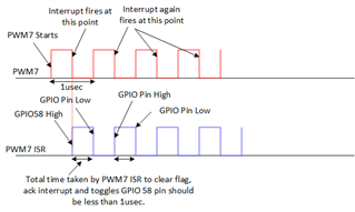
According to TRM, interrupt latency is 14 sysclock cycles. With my F20049C operating at 100Mhz, the ISR should trigger within 140nsec.

Similarly, the ISR should process the request in less than 1usec and be ready to trigger again upon the next interrupt, which arrives after 1usec. Here is my ISR code

 __interrupt void epwm7ISR(void)

{

    GPIO_writePin(myGPIO0, 1);       // GPIO58 is high

    EPWM_clearEventTriggerInterruptFlag(myEPWMTRG_BASE);

   //

    // Acknowledge this interrupt to receive more interrupts from group 3

    //

    Interrupt_clearACKGroup(INTERRUPT_ACK_GROUP3);


    GPIO_writePin(myGPIO0, 0);       // GPIO58 is low

}


Additionally, I have set the GPIO pin configuration as below.     

    GPIO_setQualificationPeriod(56,1); //  56 for GPIO56 to GPIO63


    GPIO_setQualificationMode(58 , GPIO_QUAL_SYNC);


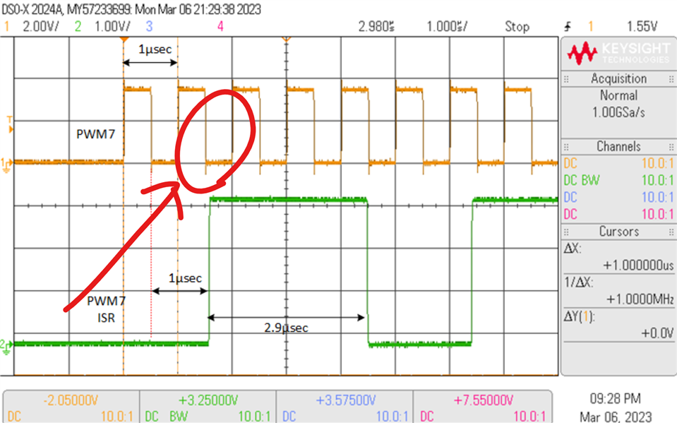
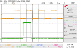
Instead when I try it on the actual hardware this is the best I could achieve.

Here, the interrupt latency is almost 1usec, and the ISR execution time is 2.9usec.

I want to know if it is normal behavior of F280049C operating at 100Mhz. I need a <1usec resolution to read the outputs of CMPSS on the comparator section and be ready to reread those outputs after 1usec. But with this behavior, I cannot get a <1usec reading resolution.


Help anyone.

 Regards

 Shahamat

  • the interrupt latency is almost 1usec

    Can you walk me through how you calculated the INTERRUPT LATENCY? as in the moment the interrupt condition was active to when you entered the ISR?

  • Thankyou Eskandari for a quick response.

    The minimum internal interrupt latency for F280049C at 100MHz is 140nsec (14 cycles), but the first instruction execution in the ISR and assertion of GPIO pin takes about 1usec. I just wanted to get clear about what is causing this delay. I have made sure that no other higher priority interrupt is active other than ePWM7. 

    Regards   

  • It may be the driverlib GPIO_writePin taking a bit longer since the driverlib function does some math to figure out which GPIO register it needs to write to.

    BUT 1us seems too long. It almost looks like you are generating your interrupt on:

  • When I decrease the PWM frequency or increase the PWM pulse width to 4usec, the interrupt fires where it is intended. i.e., precisely in the middle of the first PWM pulse and so on. 

  • Can you share the scope capture?

  • This is the case when I increase the PWM pulse width to 2usec (Yellow waveform). The interrupt response time and the point where the GPIO asserts (green waveform) is after 500nsec from the center of the PWM. Here again the ISR takes 2.9usec to complete.

    However if I reduce the ISR to 

     __interrupt void epwm7ISR(void)

    {

        GPIO_writePin(myGPIO0, 1);       // GPIO58 is high

         GPIO_writePin(myGPIO0, 0);       // GPIO58 is low

    }

    where I don't reset the interrupt flag and don't acknowledge the interrupt. the ISR execution time reduces to almost 1usec as shown below. 


    Regards

    Shahamat

  • I see show me your EPWM interrupt configuration. Let's validate that is correct.

  • These are the snapshots of the sysconfig screen for PWM7

    As a result, the EPWM pin configuration is as folows

        //

        // EPWM7 -> myEPWMTRG Pinmux

        //

        GPIO_setPinConfig(GPIO_12_EPWM7_A);

        GPIO_setPadConfig(myEPWMTRG_EPWMA_GPIO, GPIO_PIN_TYPE_STD);

        GPIO_setQualificationMode(myEPWMTRG_EPWMA_GPIO, GPIO_QUAL_SYNC);

    And these are the settings for the EPWM interrupt created due to the configuration made in sysconfig.

      EPWM_enableInterrupt(myEPWMTRG_BASE);   

        EPWM_setInterruptSource(myEPWMTRG_BASE, EPWM_INT_TBCTR_U_CMPA); 

        EPWM_setInterruptEventCount(myEPWMTRG_BASE, 1); 

        // This is the GPIO Pin Configuration made in the main program which I made.

        //

        Device_initGPIO();

        GPIO_setQualificationPeriod(56,1);

        //GPIO_setQualificationPeriod(57,1);

        //GPIO_setQualificationPeriod(58,1);

        //GPIO_setQualificationPeriod(59,1);

        GPIO_setQualificationMode(58 , GPIO_QUAL_SYNC);

        //GpioCtrlRegs.GPACTRL.all = 0x00000000;

        //GpioCtrlRegs.GPBCTRL.all = 0x00000000;

    Regards

    Shahamat

  • Can you share your action qualifier settings as well?

  • Here are the Action qualifiers settings.

    Since I use only PWM7A therefore I have not configured the PWM7B.

    Regards

    Shahamat.

  • You generate EPWM Interrupt on CMPA UP event. You also set the EPWM output HIGH on EPWM CMPA U event. 

  • Wouldn't that make this the ISR delay to GPIO?

  • That is right. The ISR delay is due to GPIO functions in the ISR. I have looked into 

        GPIO_writePin(myGPIO0, 1);       // GPIO58 is high

    function. It is causing all the delay. What do you suggest I should do to reduce this delay? Moreover, I need to implement a six-state, state machine within this ISR, and I need it to be completed within 1usec and return the results. Any idea on how to tackle it?

    Regards

    Shahamat

  • So first option is to use the RELEASE version of the driverlib as opposed to the DEBUG version of the driverlib. The release version has OPTIMIZATION from the compiler turned on. The next step is to turn on the optimizations for your application project.

    Another thing you can do is write directly to the register for the GPIO you wish to set/clear.

    REPLACE using GPIO_writePin (which does all of the items below):

    with a HWREG write like below:

    HWREG(GPIODATA_BASE + GPIO_O_GPBSET) = GPIO_GPBSET_GPIO58

  • Do you recomend going to assembly language to implement the ePWM7 ISR? 

  • No need to use Assembly. Use C to write directly to the register location if you need the SW execution of specific functions to be faster.

  • Thankyou Eskamdari. 

    Could you please share some resources on using C to work directly at the register level? It would help me a lot.  

    Thanx in advance

  • do we have a documentaiton on how to use HWREG to access registers?

  • The driverlib API guide would be helpful -

    Programming Models — F28002x API Guide (ti.com)

    In addition, I recommend you set the project optimization level to O2 or higher. GPIO_writePin is an inline function and hence will be compiled as part of your application code and uses application optimization settings. Also, remove the 'DEBUG' predefined symbol to remove the ASSERT checks.

    Regards,

    Veena

  • Hi Shahamat,

    Why not try CLA for PWM drive or GPIO configuration processed at the CPU level? Especially If HWREG and release library optimizations do not speed up GPIO toggle rate. Seemingly we can't rely on a GPIO port to indicate ePIE ISR latency to ePWM output pulse edge times to be entirely accurate. A 1µs pulse width pends IRQ's at the same rate and GPIO edges may fall behind in ePIE peripheral core priority order, check TRM interrupts tables. There are some CLA examples of GPIO configurations to pull code from.

  • Thanx for the TIps GI and Veena. 

    Let me be more specific about my problem statement. The GPIO toggle within the ISR was just a test to check to ISR response time, and judging by the time it takes to respond, I got into a kind of closed end.

    I am reading the outputs of 6 CMPSS (which produce their comparison results from the outputs of 3 PGAs). I am using an additional PWM7 with a pulse width of 1usec, and in the middle of this PWM7, the ISR fires up. Within this ISR, I am planning to implement a state machine with 6 states which will read this data from CMPSS output and decide the next state. I was pretty confident that the high clocking rate of my controller would allow me to implement this state machine using a case statement and give me the next state output before the ISR fires again after 1 usec. 

    Do you agree with my approach or is there a smarter way to accomplish this within a 1 usec window?

    Regards

    Shahamat

  •  

    In case I didn't clarify myself, I am posting this figure of what I need to implement.

  • I am reading the outputs of 6 CMPSS (which produce their comparison results from the outputs of 3 PGAs).

    That seemingly will add propagation delay into CMPSS outputs. The CMP's could be placed directly on a phase to eliminate such added delays. This method has been tested to give 1µs ePWM OSHT trip shut down or CBC trips driven by CMPSS ISR until the problem has been mitigated.  

    I am using an additional PWM7 with a pulse width of 1usec, and in the middle of this PWM7, the ISR fires up.

    Perhaps you could add blanking cycles into ePWM configuration to control the CMPSS response ISR timing to be on the rising edge. Then again the CPMSS input would be more effective to be on the phase, not the PGA output.  

    Best of luck on your project Relaxed