Because of the holidays, TI E2E™ design support forum responses will be delayed from Dec. 25 through Jan. 2. Thank you for your patience.

This thread has been locked.

If you have a related question, please click the "Ask a related question" button in the top right corner. The newly created question will be automatically linked to this question.

TMS320F280025: Using XDS 110 debug Probe connecting for communication

Part Number: TMS320F280025
Other Parts Discussed in Thread: CONTROLSUITE

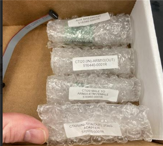
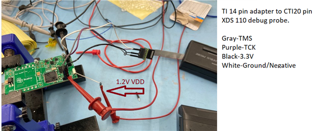
We are Using the TMDSEMU-110U debug tool. Our PCB does not have a USB connector but rather headers with SCI comms. We are able to flash the device with the JTAG !T 14 adapter and supplying TMS, TCK, GND, and 3.3V, however I am not sure how to set it up for "Monitor and Tune". We have tried connecting the AUX cable and breakout board for Uart but we are still getting a time out and simply cannot connect to the target. What to get serial comms what should be the physical setup and what changes (if any) need to be made in the configuration file. I put our working setup for flashing as well as the adapters we have available. Any help would be appreciated!
  • Hi Joshua,

    What do you mean by setting it up for "Monitor and Tune"? Are you trying to make a connection for running TI C2000 MATLAB/Simulink Models in External Mode?

    Which device pins are available on your headers? 

    Best Regards,

    Ben Collier

  • Thank you so much for the response! We have a serial Rx and TX as well as CAN hi and Lo. We tried hooking a FTDI from the computer however I think simulink is still trying to connect through the debugger, so if an adapter would work it would be much better. 

    Yes we are trying to set it up with simulink.
  • Hi Joshua,

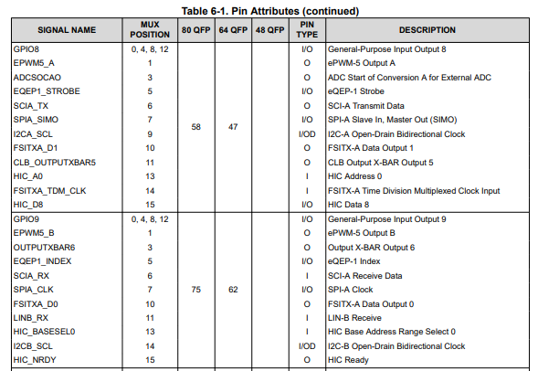
    Could you please let me know the numbers of the device pins that are available on ypur board headers? For example, SCIA_RX could be routed to many different pins on some packages. The below table from the datasheet shows that SCIA_RX could be routed to pin 75 on the 80 pin QFP package, but it could also be routed to other device pins, depending on the user settings. Please also let me know which package you are using. I want to see if I am able to connect to simulink while using the same device pins that you have available. 

    Best Regards,

    Ben Collier

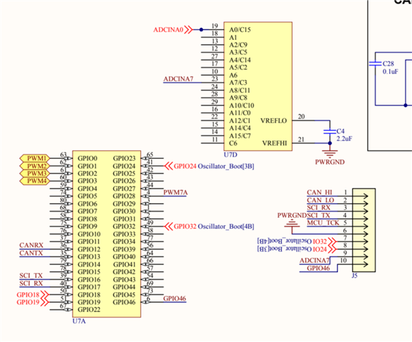
  •  The U7's are the MCU we had to break it into two different blocks. We also have the TMS320F280025C launchpad as well. I would ideally like to see if I can get the monitor and tune to work (without USB direct connect) through the debugger to work on the launchpad. I have also tried using an FTDI to USB adapter (without debug probe) with Rx, TX, and power connected but also have had issues. I think knowing all the signals that I need to get the launchpad to work without isolation would at least let me know if the design is missing something or if it is just setup issue. Thank you for your support!

  • Hi Joshua,

    Which device pins are the CAN_HI, CAN_LO, and MCU_TCK signals routed to? 

    Best Regards,

    Ben Collier

  • For our Board CAN Hi and CAN Lo are going to the CAN Tranciever (ISO1050DW) The MC_TCK is going to PIN 45 of the MCU. For Now we are just trying to get it to work on the launchpad without the USB. 

    How should it be set up if we are isolating the USB and using the headers for the launchpad? If I can verify that set up first I will at least know issue is with our design.

  • Hi,

    I will need a couple days to look into how to connect to the launchpad with Simulink, without using the usb connection. I will let you know when I have found an answer.

    Best Regards,

    Ben Collier

  • Hi Joshua,

    I have ran into some roadblocks and have been unable to make substantial progress on this issue. Have you contacted Mathworks support about this, since the issue seems to mostly involve connecting to their software? 

    Best Regards,

    Ben Collier

  • I contacted them initially, and was told that FTDI serial and ground should be all that is necessary to connect to there software. I tried connecting directly but was getting an XDS110 error (I didn't use it). So I thought messaging TI might be better option. I have different adapters to use, however I'm not really sure which one and which signals to use. Previously, I tried UART breakout adapter, but didn't have any success. 

  • Hi Joshua,

    Could you share with me the place that you saw that "FTDI serial and ground should be all that is necessary" ?

    The instructions that I am finding for connecting to C2000 devices with Simulink suggest that you would need an FTDI chip acting as an interface between USB and JTAG/SCI: 

    https://www.mathworks.com/matlabcentral/answers/751519-quick-troubleshooting-guide-executing-ti-c2000-simulink-models-in-external-mode

    There may be an important connection between the FTDI chip and the SCI pins on the C2000 device, and this connection may not be possible on a standalone XDS110. I can check this on the schematic of the F28379D Launchpad, which they reference at the above link, and I will get back to you tomorrow. If you are also curious, you can find the F28379D schematic in the C2000 ControlSUITE software package.

    One other thing, have you found any examples of people connecting to their C2000 devices in simulink with standalone JTAG debug probes? I'm worried that you will need to use an onboard FTDI chip to translate between your host PC and the C2000 device.

    Best Regards,

    Ben Collier 

  • Hi,

    I apologize for the delay in my response. I am still not sure how to connect to the C2000 device using an external JTAG debug probe, since I cannot find any examples, but it should be possible.  

    This post mentions that you will need a UART connection with the C2000 device to connect with Simulink: https://www.mathworks.com/matlabcentral/answers/751519-quick-troubleshooting-guide-executing-ti-c2000-simulink-models-in-external-mode\

    In section 2, it also mentions how the correct GPIOs must be set up to use UART.

    Page 9-10 of this document mentions how to use the XDS110 to make a UART connection: https://www.ti.com/lit/ug/sprui94/sprui94.pdf?ts=1681510638013&ref_url=https%253A%252F%252Fwww.google.com%252F

    Could you try connecting the UARTTX and UARTRX pins from the XDS110 (mentioned in the above page) to the GPIOs being used for serial communication on the board?

    Best Regards,

    Ben Collier