Other Parts Discussed in Thread: C2000WARE
Greetings,
I am trying to connect MPU9250 to TMS320F28379D through SPI. However I am facing a problem reading from the IMU. the value of the reading buffer are not changing. Also, when i set the Transmit FIFO Interrupt Level Bits to 1 before entering the while loop it did not work. so I kept it 2. and I sent the register address twice. I am not sure if the problem with the launchpad cause to connect the IMU to I2C i needed to put external pull up circuit as I saw the recommendations. but I couldn't find anything similar for the SPI. and I did not find any similar problem to mine. the code is attached below. I am using both CPUs but the code of the CPU2 is not related so i will only attach the code of CPU1. I checked the bitfiled examples in C2000Ware_4_02_00_00, but all the examples are loopback examples.
thanks in advance,
#include "F28x_Project.h"
#include <math.h>
//#include"KF.h"
#include "UKF_IMU.h"
#include "F28x_Project.h"
#include "F2837xD_Ipc_drivers.h"
//
//SPI connected with MPU9250 "IMU"
//
//
// define the address of each register from the MPU-9250 Register Map and Descriptions Revision 1.6.pdf
//
#define MPU9250_SMPLRT_DIV 0x0019
#define MPU9250_CONFIG 0x001A
#define MPU9250_GYRO_CONFIG 0x001B
#define MPU9250_ACCEL_CONFIG 0x001C
#define MPU9250_ACCEL_CONFIG2 0x001D
#define MPU9250_ACCEL_XOUT_H 0x003B
#define MPU9250_ACCEL_XOUT_L 0x003C
#define MPU9250_ACCEL_YOUT_H 0x003D
#define MPU9250_ACCEL_YOUT_L 0x003E
#define MPU9250_ACCEL_ZOUT_H 0x003F
#define MPU9250_ACCEL_ZOUT_L 0x0040
#define MPU9250_GYRO_XOUT_H 0x0043
#define MPU9250_GYRO_XOUT_L 0x0044
#define MPU9250_GYRO_YOUT_H 0x0045
#define MPU9250_GYRO_YOUT_L 0x0046
#define MPU9250_GYRO_ZOUT_H 0x0047
#define MPU9250_GYRO_ZOUT_L 0x0048
#define MPU9250_USER_CTRL 0x006A
#define MPU9250_PWR_MGMT_1 0x006B
#define DEG_RAD 0.017453292
//
// function to initialize timer0
//
void Ini_timer0(void);
//
// function to initialize SPI peripheral
//
void spi_fifo_init(void);
//
// reading the Accelerometer data
//
void ACC_A(double x_dd, double y_dd, double z_dd);
//
// interrupt function of SPI
//
__interrupt void spiTxFifoIsr(void);
__interrupt void spiRxFifoIsr(void);
//
// interrupt function to store data
//
__interrupt void IPPC0_ISR(void);
Uint16 FailCount;
Uint16 Send_sensor_regs,Ind;
//
// Function Prototypes
//
struct SPIMsgIn {
Uint16 sensor_Reg;
int16 MsgBuffer[12];
};
struct SPIMsgOut {
Uint16 MPU9250_Reg;
Uint16 outMsg;
};
struct SPIMsgIn *CurrentMsgPtr;
struct SPIMsgOut *CurrentMsgPtrW;
Uint16 SPI_WriteData(struct SPIMsgOut *msg);
void SPI_ReadData(Uint16 msg);
int i,j,k,k1,k2,k3,k4,k5,a,f;
double dx,dy,dz,accX,accY,accZ;
double dx_f,dy_f,dz_f,accX_f,accY_f,accZ_f,tt,ts;
double in_buffer[6][20];
double temp1,temp2,temp3,temp4,temp5,temp6;
double roll,pitch,KF_roll,KF_pitch,AR;
int GGG, counter2;
int go;
int go2;
int transmit;
Uint32 cpusend;
UKF R_UKF,P_UKF;
void main(void)
{
struct SPIMsgIn SPI_Msgin;
struct SPIMsgOut SPI_Msgout;
//
// Initialize System Control:
//
InitSysCtrl();
//
// initialize GPIO
//
InitGpio();
//
// connect SCIB with CPU2 for Bluetooth connection
//
EALLOW;
DevCfgRegs.CPUSEL5.bit.SCI_B =1;
EDIS;
//
// Give CPU2 Control of the GPIO19 and GPIO18
//
GPIO_SetupPinMux(19, GPIO_MUX_CPU2, 2);
GPIO_SetupPinOptions(19, GPIO_INPUT, GPIO_PUSHPULL);
GPIO_SetupPinMux(18, GPIO_MUX_CPU2, 2);
GPIO_SetupPinOptions(18, GPIO_OUTPUT, GPIO_ASYNC);
//
//Clear all interrupts and initialize PIE vector table:
//
DINT;
//
// Initialize PIE control registers to their default state.
//
InitPieCtrl();
//
// Disable CPU interrupts and clear all CPU interrupt flags:
//
IER |= 0x0000;
IFR=0x0000;
//
//clear the IPC flag
//
IpcRegs.IPCCLR.bit.IPC0= 1;
//
//clears it and allows another interrupt from the corresponding group to propagate
// it is not important here as after after every single interrupt function
//
// PieCtrlRegs.PIEACK.all = PIEACK_GROUP1;
// PieCtrlRegs.PIEACK.all = PIEACK_GROUP6;
PieCtrlRegs.PIEACK.all = 0x0061;
//
// Initialize the PIE vector table with pointers to the shell Interrupt
// Service Routines (ISR)
//
InitPieVectTable();
//
// Interrupts that are used in this example are re-mapped to
// ISR functions found within this file.
//
EALLOW; // This is needed to write to EALLOW protected registers
PieVectTable.IPC0_INT = &IPPC0_ISR; // assign interrupt function of IPC0
PieVectTable.SPIA_RX_INT = &spiRxFifoIsr;//assign interrupt function of SPIA RX
PieVectTable.SPIA_TX_INT = &spiTxFifoIsr;//assign interrupt function of SPIA TX
EDIS; // This is needed to disable write to EALLOW protected registers
//
//Enable vector fetching from ePIE block. This bit must be set to 1 for peripheral interrupts to work.
//
EALLOW;
PieCtrlRegs.PIECTRL.bit.ENPIE = 1;
IER |= M_INT1;
EINT;
EDIS;
//
//clear IPC flags
//
IpcRegs.IPCCLR.all= 0xFFFFFFFF;
//
//enable IPC Interrupts IN the PIE
//
PieCtrlRegs.PIEIER1.bit.INTx13= 1;
//
// Enable CPU INT13 which is connected to Timer1 interrupt:
//
IER |= M_INT13;
EINT;
//
//enable timer1 interrupts IN PIE
//
PieCtrlRegs.PIEIER1.bit.INTx7=1;
//
// Enable CPU INT7 which is connected to Timer1 interrupt:
//
IER |= M_INT7;
EINT;
//
// Enable SPIA_RX,SPIA_TX __interrupt 1,2 in the PIE: Group 6 __interrupt 1,2 table page 102 manul
//
PieCtrlRegs.PIEIER6.bit.INTx1=1;
PieCtrlRegs.PIEIER6.bit.INTx2=1;
//
// Enable CPU INT6 which is connected to PIE group 6
//
IER |= M_INT6;
EINT; // Enable Global interrupt INTM
ERTM; // Enable Global realtime interrupt DBGM
//
//SPI initialization
//
spi_fifo_init();
//
//timer0 initialization
//
Ini_timer0();
//
//wait here until CPU2 is ready
//
while(IpcRegs.IPCSTS.bit.IPC17 != 1)
{
}
IpcRegs.IPCACK.bit.IPC17 = 1;
//
// set CurrentMsgPtrW as the message output structure defined in 81 to 86
//
CurrentMsgPtrW= &SPI_Msgout;
//
// set I2C_IF_DIS bit to '1' in the USER_CTRL register,
// to disable I2C and work with SPI
//
CurrentMsgPtrW->MPU9250_Reg= MPU9250_USER_CTRL;
CurrentMsgPtrW->outMsg=0x10;
FailCount=SPI_WriteData(CurrentMsgPtrW);
while(SpiaRegs.SPIFFTX.bit.TXFFINT!=1) {}
//
// Auto selects the best available clock source,
// else use the Internal oscillator 20 MHZ
//
CurrentMsgPtrW->MPU9250_Reg=MPU9250_PWR_MGMT_1;
CurrentMsgPtrW->outMsg=0x01;
FailCount= SPI_WriteData(CurrentMsgPtrW);
while(SpiaRegs.SPIFFTX.bit.TXFFINT!=1) {}
//
// set the SMPLRT_DIV to 7 that mean the sample rate = internal sample rate / (7+1)
// therefore the samplerate will be 10 MHZ/8 = 1.25 MHZ
//
CurrentMsgPtrW->MPU9250_Reg= MPU9250_SMPLRT_DIV;
CurrentMsgPtrW->outMsg=0x07;
FailCount=SPI_WriteData(CurrentMsgPtrW);
while(SpiaRegs.SPIFFTX.bit.TXFFINT!=1) {}
//
// Enables the FSYNC pin data to be sampled at the ACCEL_ZOUT_L[0]
//
CurrentMsgPtrW->MPU9250_Reg= MPU9250_CONFIG;
CurrentMsgPtrW->outMsg=0x3E;
FailCount=SPI_WriteData(CurrentMsgPtrW);
while(SpiaRegs.SPIFFTX.bit.TXFFINT!=1) {}
//
// set the Bandwidth (Hz) of the digital low pass filter to 5 Hz for the gyro and
// the 1000 degree per second
//
CurrentMsgPtrW->MPU9250_Reg= MPU9250_GYRO_CONFIG;
CurrentMsgPtrW->outMsg=0x10;
FailCount= SPI_WriteData(CurrentMsgPtrW);
while(SpiaRegs.SPIFFTX.bit.TXFFINT!=1) {}
//
// Acceleration Full Scale Select to +-2g [4:3]= "00"
//
CurrentMsgPtrW->MPU9250_Reg= MPU9250_ACCEL_CONFIG;
CurrentMsgPtrW->outMsg=0x00;
FailCount=SPI_WriteData(CurrentMsgPtrW);
while(SpiaRegs.SPIFFTX.bit.TXFFINT!=1) {}
//
// set the Bandwidth (Hz) of the digital low pass filter to 5 HZ for the accelerometer
//
CurrentMsgPtrW->MPU9250_Reg= MPU9250_ACCEL_CONFIG2;
CurrentMsgPtrW->outMsg=0x0E;
FailCount=SPI_WriteData(CurrentMsgPtrW);
while(SpiaRegs.SPIFFTX.bit.TXFFINT!=1) {}
// SpiaRegs.SPICCR.bit.SPISWRESET = 0;
//SpiaRegs.SPIFFTX.all = 0xC021;
// SpiaRegs.SPIPRI.bit.FREE = 1;
//SpiaRegs.SPICCR.bit.CLKPOLARITY = 0;
//SpiaRegs.SPICCR.bit.SPICHAR = 7; // 8 bit word length
//SpiaRegs.SPICTL.bit.TALK = 1; // Enable Transmit path
// SpiaRegs.SPICCR.bit.SPISWRESET = 1;
SPI_Msgin.MsgBuffer[0] = 0x0000;
SPI_Msgin.MsgBuffer[1] = 0x0000;
SPI_Msgin.MsgBuffer[2] = 0x0000;
SPI_Msgin.MsgBuffer[3] = 0x0000;
SPI_Msgin.MsgBuffer[4] = 0x0000;
SPI_Msgin.MsgBuffer[5] = 0x0000;
SPI_Msgin.MsgBuffer[6] = 0x0000;
SPI_Msgin.MsgBuffer[7] = 0x0000;
SPI_Msgin.MsgBuffer[8] = 0x0000;
SPI_Msgin.MsgBuffer[9] = 0x0000;
SPI_Msgin.MsgBuffer[10] = 0x0000;
SPI_Msgin.MsgBuffer[11] = 0x0000;
/*
// Clear incoming message buffer
for (int rr = 0; rr < 12; rr++)
{SPI_Msgin.MsgBuffer[rr] = 0x0000;}
*/
i=0;k=0;
CpuTimer1Regs.TCR.bit.TRB=1;
CpuTimer1Regs.TCR.bit.TSS=0;
//R_UKF.setAngle(0.00); // First set roll starting angle
// P_UKF.setAngle(0.00); // Then pitch
//f=1;
while(1)
{
CpuTimer0Regs.TCR.bit.TRB=1;
CpuTimer0Regs.TIM.all=0xFFFFFFFF;
CpuTimer0Regs.TCR.bit.TSS=0;
tt= CpuTimer0Regs.TIM.all;
CurrentMsgPtr= &SPI_Msgin;
CurrentMsgPtr->sensor_Reg=MPU9250_GYRO_XOUT_H;
SpiaRegs.SPIFFTX.bit.TXFFINTCLR=1; // Clear Interrupt flag
SpiaRegs.SPIFFRX.bit.RXFFOVFCLR=1; // Clear Overflow flag
SpiaRegs.SPIFFRX.bit.RXFFINTCLR=1; // Clear Interrupt flag
while(f==1)
{
switch(i)
{
case 0:CurrentMsgPtr->sensor_Reg=MPU9250_GYRO_XOUT_H;
f=0;
break;
case 1:CurrentMsgPtr->sensor_Reg=MPU9250_GYRO_XOUT_L;
f=0;
break;
case 2: dx=((CurrentMsgPtr->MsgBuffer[0] << 8) | CurrentMsgPtr->MsgBuffer[1]);
dx=(dx/131)*DEG_RAD;
in_buffer[0][k]=dx;
k=k+1;
go2= 32;
f=0;
CurrentMsgPtr->sensor_Reg=MPU9250_GYRO_YOUT_H;
break;
case 3: CurrentMsgPtr->sensor_Reg=MPU9250_GYRO_YOUT_L;
f=0;
break;
case 4: dy=((CurrentMsgPtr->MsgBuffer[2] << 8) | CurrentMsgPtr->MsgBuffer[3]);
dy=(dy/131)*DEG_RAD;
in_buffer[1][k1]=dy;
k1=k1+1;
f=0;
CurrentMsgPtr->sensor_Reg=MPU9250_GYRO_ZOUT_H;
break;
case 5: CurrentMsgPtr->sensor_Reg=MPU9250_GYRO_ZOUT_L;
f=0;
break;
case 6: dz=((CurrentMsgPtr->MsgBuffer[4] << 8) | CurrentMsgPtr->MsgBuffer[5]);
dz=(dz/131)*DEG_RAD;
in_buffer[2][k2]=dz;
CurrentMsgPtr->sensor_Reg=MPU9250_ACCEL_XOUT_H;
k2=k2+1;
f=0;
break;
case 7: CurrentMsgPtr->sensor_Reg=MPU9250_ACCEL_XOUT_L;
f=0;
break;
case 8: accX=((CurrentMsgPtr->MsgBuffer[6] << 8) | CurrentMsgPtr->MsgBuffer[7]);
accX=accX;
in_buffer[3][k3]=accX;
k3=k3+1;
f=0;
CurrentMsgPtr->sensor_Reg=MPU9250_ACCEL_YOUT_H;
break;
case 9: CurrentMsgPtr->sensor_Reg=MPU9250_ACCEL_YOUT_L;
f=0;
break;
case 10: accY=((CurrentMsgPtr->MsgBuffer[8] << 8) | CurrentMsgPtr->MsgBuffer[9]);
accY=accY;
in_buffer[4][k4]=accY;
CurrentMsgPtr->sensor_Reg=MPU9250_ACCEL_ZOUT_H;
k4=k4+1;
f=0;
break;
case 11: CurrentMsgPtr->sensor_Reg=MPU9250_ACCEL_ZOUT_L;
f=0;
break;
case 12: accZ=((CurrentMsgPtr->MsgBuffer[10] << 8) | CurrentMsgPtr->MsgBuffer[11]);
accZ=accZ;
in_buffer[5][k5]=accZ;
CurrentMsgPtr->sensor_Reg=MPU9250_GYRO_XOUT_H;
k5=k5+1;
i=0;
f=0;
break;
}
}
Send_sensor_regs= CurrentMsgPtr->sensor_Reg; // transmits data
// while(SpiaRegs.SPIFFTX.bit.TXFFST!=1) {}
SPI_ReadData(Send_sensor_regs);
while(SpiaRegs.SPIFFRX.bit.RXFFINT!=1) {}
//
// implement average filter
//
for( j=0;j<20;j++)
{
temp1+=in_buffer[0][j];
temp2+=in_buffer[1][j];
temp3+=in_buffer[2][j];
temp4+=in_buffer[3][j];
temp5+=in_buffer[4][j];
temp6+=in_buffer[5][j];
}
dx_f=temp1/20;//0.006667
temp1=0;
dy_f=(temp2/20);//+0.148;
temp2=0;
dz_f=temp3/20;
temp3=0;
accX_f=temp4/20;
temp4=0;
accY_f=temp5/20;
temp5=0;
accZ_f=temp6/20;
temp6=0;
if(k>=20)
{k=0;}
if(k1>=20)
{k1=0;}
if(k2>=20)
{k2=0;}
if(k3>=20)
{k3=0;}
if(k4>=20)
{k4=0;}
if(k5>=20)
{k5=0;}
ACC_A(accX_f,accY_f,accZ_f);
// ACC_A(accX,accY,accZ);
if ((roll < -1.5708 && KF_roll > 1.5708) || (roll > 1.5708 && KF_roll < -1.5708))
{
//kalmanX.setAngle(roll);
R_UKF.setAngle(roll);
KF_roll = roll;
}
else
// KF_roll = kalmanX.getAngle(roll, dx_f, ts); // Calculate the angle using a Kalman filter
{ KF_roll=R_UKF.EstimatUKF(roll, dx_f, ts);
AR=KF_roll-0.72;
cpusend= AR*100;
}
// if (abs(KF_roll) > 1.5708)
// { dy_f = -dy_f; }// Invert rate, so it fits the restricted accelerometer reading
// KF_pitch = P_UKF.EstimatUKF(pitch, dy_f, ts);
ts= 0.00000001*(tt-CpuTimer0Regs.TIM.all);
}
}
void Ini_timer0()
{
EALLOW; // This is needed to write to EALLOW protected registers
CpuSysRegs.PCLKCR0.bit.CPUTIMER0=1;
CpuTimer0Regs.TIM.all=0xFFFFFFFF;
CpuTimer0Regs.PRD.bit.LSW=0xFFFF;
CpuTimer0Regs.PRD.bit.MSW=0xFFFF;
CpuTimer0Regs.TCR.bit.TIE=0;
CpuTimer0Regs.TCR.bit.TIF=1;
CpuTimer0Regs.TCR.bit.TSS=0;
CpuTimer0Regs.TCR.bit.TRB=1;
CpuTimer0Regs.TCR.bit.FREE=1;
CpuTimer0Regs.TCR.bit.SOFT=0;
CpuTimer0Regs.TPR.bit.TDDR=0x00;
CpuTimer0Regs.TPR.bit.PSC=0x0000;
CpuTimer0Regs.TPRH.bit.TDDRH=0x00;
EDIS;
}
Uint16 SPI_WriteData(struct SPIMsgOut *msg)
{
SpiaRegs.SPITXBUF = msg->MPU9250_Reg;
SpiaRegs.SPITXBUF =msg->outMsg;// Master transmits data
return 0;
}
void SPI_ReadData (Uint16 msg)
{
go++;
SpiaRegs.SPICCR.bit.SPISWRESET = 0;
SpiaRegs.SPICTL.bit.TALK = 1; // Enable Transmit path
SpiaRegs.SPICCR.bit.SPISWRESET = 1;
SpiaRegs.SPITXBUF = msg;
SpiaRegs.SPITXBUF = msg;
f=1;
while(SpiaRegs.SPIFFTX.bit.TXFFINT!=1) {}
}
__interrupt void IPPC0_ISR(void)
{
IpcRegs.IPCACK.bit.IPC0 =1; // clear IPC flag
GGG = 15;
counter2++;
}
//
void ACC_A(double x_dd, double y_dd, double z_dd)
{
float ss;
roll = atan2(y_dd,-z_dd);
ss=pow(z_dd*z_dd + y_dd*y_dd,0.5);
// pitch = atan2(x_dd,sqrt(y_dd*y_dd + z_dd*z_dd))/DEG_RAD;
if (y_dd<0)
{
pitch=(atan(x_dd/-ss));
}
else
{
pitch=(atan(x_dd/ss));
}
//pitch=pitch/DEG_RAD;
}
void spi_fifo_init()
{
EALLOW;
//
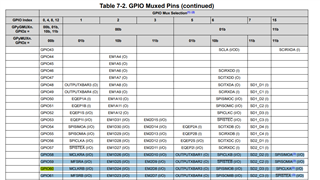
//J2 ....(19"SPICS" ,14"SPISIMO",15"SPI), J1.....(7"SPICLK") "GPIO 58-61"
//
//
// Enable pull-up on
//
GpioCtrlRegs.GPBPUD.bit.GPIO58 = 0;
GpioCtrlRegs.GPBPUD.bit.GPIO59 = 0;
GpioCtrlRegs.GPBPUD.bit.GPIO60 = 0;
GpioCtrlRegs.GPBPUD.bit.GPIO61 = 0;
//
// Set qualification for selected pins to asynch only
//
GpioCtrlRegs.GPBQSEL2.bit.GPIO58 = 3; // Asynch input GPIO58 (SPISIMOA)
GpioCtrlRegs.GPBQSEL2.bit.GPIO59 = 3; // Asynch input GPIO59 (SPISOMIA)
GpioCtrlRegs.GPBQSEL2.bit.GPIO60 = 3; // Asynch input GPIO60 (SPICLKA)
GpioCtrlRegs.GPBQSEL2.bit.GPIO61 = 3; // Asynch input GPIO61 (SPISTEA)
//
//Configure SPI-A pins using GPIO regs
//
GpioCtrlRegs.GPBMUX2.bit.GPIO60=1;GpioCtrlRegs.GPBMUX2.bit.GPIO58=1;
GpioCtrlRegs.GPBMUX2.bit.GPIO61=1;GpioCtrlRegs.GPBMUX2.bit.GPIO59=1;
//GpioCtrlRegs.GPBGMUX2.bit.GPIO60=1;GpioCtrlRegs.GPBGMUX2.bit.GPIO58=1;
// GpioCtrlRegs.GPBGMUX2.bit.GPIO61=1;GpioCtrlRegs.GPBGMUX2.bit.GPIO59=1;
EDIS;
//
//
// Initialize SPI FIFO registers
//
SpiaRegs.SPICCR.bit.SPISWRESET = 0;
SpiaRegs.SPIFFTX.all = 0xC022; // Enable FIFOs, set TX FIFO level to 2
SpiaRegs.SPIFFRX.all = 0x0021; // Set RX FIFO level to 1
SpiaRegs.SPIFFCT.all = 0x00;
//InitSpi();
//
// Initialize core SPI registers
//
// Initialize SPI-A
// Set reset low before configuration changes
// Clock polarity (0 == rising, 1 == falling)
// 16-bit character
// Enable loop-back
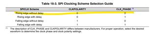
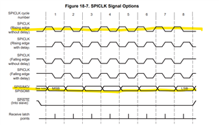
SpiaRegs.SPICCR.bit.CLKPOLARITY = 0;
SpiaRegs.SPICCR.bit.SPICHAR = 7; // 8 bit word length
SpiaRegs.SPICCR.bit.SPILBK = 0;
ClkCfgRegs.LOSPCP.bit.LSPCLKDIV = 0; // Prescaler - need 7-12 Mhz on module clk
SpiaRegs.SPICCR.bit.HS_MODE = 1;
SpiaRegs.SPIBRR.all = 0x5A; // here it is set to 10 MHZ
// Enable master (0 == slave, 1 == master)
// Enable transmission (Talk)
// Clock phase (0 == normal, 1 == delayed)
// SPI interrupts are disabled
SpiaRegs.SPICTL.bit.MASTER_SLAVE = 1;
SpiaRegs.SPICTL.bit.TALK = 1;
SpiaRegs.SPICTL.bit.CLK_PHASE = 0;
SpiaRegs.SPICTL.bit.SPIINTENA = 0;
// Set FREE bit
// Halting on a breakpoint will not halt the SPI
SpiaRegs.SPIPRI.bit.FREE = 1;
// Release the SPI from reset
SpiaRegs.SPICCR.bit.SPISWRESET = 1;
SpiaRegs.SPIFFRX.bit.RXFIFORESET=1;
SpiaRegs.SPIFFTX.bit.TXFIFO=1;
}
__interrupt void spiTxFifoIsr(void)
{
transmit++;
if(f==1)
{
a++;
// while(SpiaRegs.SPISTS.bit.INT_FLAG !=1) {} // Wait until data received
// CurrentMsgPtr->MsgBuffer[i]=SpiaRegs.SPIRXBUF;
// CurrentMsgPtr->MsgBuffer[i]=SpiaRegs.SPIRXBUF;
//
// SpiaRegs.SPICCR.bit.SPISWRESET = 0;
// SpiaRegs.SPICTL.bit.TALK = 0; // disable Transmit path
// SpiaRegs.SPICCR.bit.SPISWRESET = 1;
// CurrentMsgPtr->MsgBuffer[i]=SpiaRegs.SPIRXBUF;
// CurrentMsgPtr->MsgBuffer[i]=SpiaRegs.SPIRXBUF;
if(a>=20)
{
IpcRegs.IPCSENDDATA = cpusend; //write the results to IPC data register
IpcRegs.IPCSET.bit.IPC1 =1; // set the flag for CPU2
a=0;
}
}
// while(SpiaRegs.SPIFFRX.bit.RXFFINT!=1) {}
// SpiaRegs.SPIFFTX.bit.TXFFINTCLR=1; // Clear Interrupt flag
PieCtrlRegs.PIEACK.all|=0x20; // Issue PIE ACK
}
//
// spiRxFifoIsr - ISR for SPI receive FIFO
//
__interrupt void spiRxFifoIsr(void)
{
go2++;
// SpiaRegs.SPICCR.bit.SPISWRESET = 0;
//SpiaRegs.SPIFFTX.all = 0xC021;
// SpiaRegs.SPIPRI.bit.FREE = 1;
//SpiaRegs.SPICCR.bit.CLKPOLARITY = 0;
//SpiaRegs.SPICCR.bit.SPICHAR = 7; // 8 bit word length
// SpiaRegs.SPICTL.bit.TALK = 0; // Enable Transmit path
// SpiaRegs.SPICCR.bit.SPISWRESET = 1;
CurrentMsgPtr->MsgBuffer[i]=SpiaRegs.SPIRXBUF;
//CurrentMsgPtr->MsgBuffer[i]=SpiaRegs.SPIRXBUF;
i=i+1;
PieCtrlRegs.PIEACK.all|=0x20; // Issue PIE ack
}