Hi,
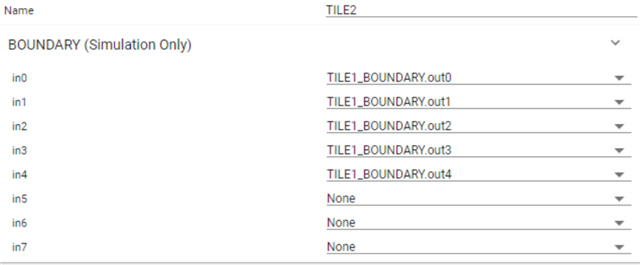
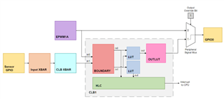
I am a newbie in the world of C2000 family. I am trying to implement something in my F28379D MCU by using the module CLB on it. I tried to connect several outputs of Tile1 to the boundary input of tile2, but as the global mux of CLB on this MCU can only have access of CLBx_OUT4/5, the number of output of each tile is limited to 2(if I clearly understood). And for other output of the tile like CLB1_OUT1, is connected to an intern signal like PWMA according to the TRM document. As I need more than 2 outputs of one CLB tile to be connected to the inputs of another CLB tile, I was wondering how I can achieve this. For instance, like this:
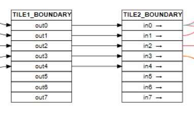
Here is my idea:
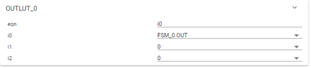
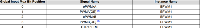
I enabled the output0 of Tile1 and configured the input0 of tile2 to the global input mux of CLB, as I see that I have access to epwmxA/B signals by routing to the global mux, and the output0 of Tile1 can override the epwm1A so I thought it can connected each other but in fact I tested but it didn't work. Here is my configuration code in main.c:
void main(void)
{
Device_init();
Device_initGPIO();
Interrupt_initModule();
Interrupt_initVectorTable();
//enable the interrupt
Interrupt_register(INT_CLB1, &clb1ISR);
Interrupt_enable(INT_CLB1);
Interrupt_register(INT_CLB2, &clb2ISR);
Interrupt_enable(INT_CLB2);
//
// Enabling EPWM1/2 to enable CLB1/2
//
SysCtl_enablePeripheral(SYSCTL_PERIPH_CLK_EPWM1);
SysCtl_enablePeripheral(SYSCTL_PERIPH_CLK_EPWM2);
//init of clbs
CLB_enableCLB(CLB1_BASE);
initTILE1(CLB1_BASE);
CLB_enableCLB(CLB2_BASE);
initTILE2(CLB2_BASE);
//
// Select Global input instead of local input for all CLB IN
//CLB2 tile2
CLB_configLocalInputMux(CLB2_BASE, CLB_IN0, CLB_LOCAL_IN_MUX_GLOBAL_IN);
//CLB2
CLB_configGlobalInputMux(CLB2_BASE, CLB_IN0, CLB_GLOBAL_IN_MUX_EPWM1A);
//CLB2 laisse les connections internes
CLB_configGPInputMux(CLB2_BASE, CLB_IN0, CLB_GP_IN_MUX_EXTERNAL);
//Config for GPIO0 for CLB1_OUT_0
GPIO_setPinConfig(GPIO_0_EPWM1A);
GPIO_setDirectionMode(0, GPIO_DIR_MODE_OUT);
GPIO_setPadConfig(0, GPIO_PIN_TYPE_STD);
//enable the override mask
CLB_setOutputMask(CLB1_BASE, 1 << 0, true);
//clear the flag
CLB_clearInterruptTag(CLB1_BASE);
CLB_clearInterruptTag(CLB2_BASE);
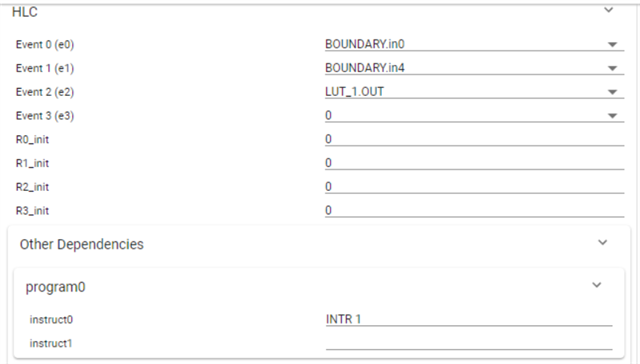
...

I didn't include all the code because it is a bit long, but my idea is clear. By enabling the output0 of tile1 and creating a corresponding GPIO, I activated the ePWM1A signal and then configured the input0 of tile2 in order to interconnect the two tiles. I tested it by using one event in HLC of tile 2 with a flag to toggle one led onboard(the output0 of tile can generate a pulse to trigger the event), but it seemed that it didn't work. I am wondering that is this due to the signal specification that we can't just put a random signal to pwm output? Or I didn't do the correct configuration. Thank you in advance for your help!