This thread has been locked.

If you have a related question, please click the "Ask a related question" button in the top right corner. The newly created question will be automatically linked to this question.

CMPSS + EPWM (Questions ABOUT PWM Generation)

HI 

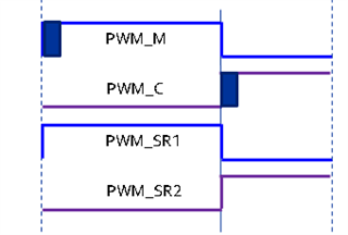
I am trying to create a switching sequence like the image below.

I'm going to use the CMPSS function. I will use the output of CMPSS to create PWM_M.

Is there a way to generate PWM_C, PWM_SR1, and PMW_SR2 in synchronization with PWM_M while using the output signal of CMPSS?

Due to the CMPSS signal, PWM_M will be set to a Low value due to EPWM's TRIP function.

But in this part, in order to set PWM_C to HIGH, PWM_M is set to LOW and I want to set it to HIGH after a certain dead time, but I'm not sure.
  • Hello,

    Correct me if my understanding is incorrect. In the image, the solid vertical line represents the trip event occurring, correct? When the trip occurs, you want PWM_M, _SR1, and _SR2 to immediately react, setting _M and _SR1 low, and _SR2 high. Then, after a pre-defined amount of time, set _C high. Is all that accurate?

    Essentially, there's no way native purely to the ePWM to cause this programmable delay. The filtering functionality of the ePWM isn't ideal for that kind of configuration. However, there is a relatively simple to implement workaround, which relies on having at least one unused GPIO to route the signal through.

    Take a look at the following configuration:

    • CMPSS CTRIPOUTx -> Output X-BAR [spare GPIO] -> Input X-BAR [the same spare GPIO] -> ePWM DC/TZ
    • CMPSS CTRIPx -> ePWM DC/TZ

    One of these signals utilizes the CMPSS internal Digital Filter to introduce a programmable delay before the ePWM trip activates, while the other signal bypasses that filter. Which does which is your choice.

    • Unfiltered signal -> ePWM DC/TZ -> PWM_M & PWM_SR1 force low; PWM_SR2 force high
    • Filtered signal -> ePWM DC/TZ -> PWM_C force high

    Essentially, the digital filter functions by waiting to adjust the output high or low until N samples (user-programmable) have changed. This means that it can effectively function as a simple programmable buffer, synchronized to the CMPSS clock. Take a look at your device's TRM for details on how to set the Digital Filter- in the F28003x TRM, it's section 18.5.

    In summary, configure the CTRIPOUTx signal of the CMPSS identically to the CTRIPx signal. Filter one of them, using that to introduce your programmable delay. Route the CTRIPOUTx signal to an unused GPIO using the Output X-BAR. Configure the Input X-BAR to take that GPIO signal to the ePWM. You now have your trip event and your delayed trip event, configuring each to act independently.

    I hope that all makes sense. Let me know if you have follow-up questions!

    Regards,
    Jason Osborn

    Side notes:

    • If you're already utilizing the digital filter in the CMPSS, that's fine- you should be able to use GPIO input qualification filtering in the same way.
    • If you don't have a spare GPIO or you don't want to use one, the other side of the CMPSS module (L/H) should be able to be inverted to generate the extra signal without requiring that spare GPIO, but this requires a little bit work & math to make sure the high/low sides remain equivalent, so I'm more fond of utilizing the X-Bars like this- it's a simple configuration, more easily adjustable, in my opinion.
      • As a third option, use a second CMPSS. This is probably the least ideal choice!
  • thanks your resolve

    CMPSS CTRIPOUTx -> Output X-BAR [spare GPIO] -> Input X-BAR [the same spare GPIO] -> ePWM DC/TZ

    In this solution, I think the output pin and the output pin should be connected.
    But I'm in a situation where I can't put out a new output pin for gpio purpose.

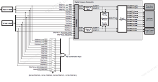
    So what about valley switching? The function of the DC module in the EPWM seems to be able to create a delay for the trip signal.


  • Hello,

    Unfortunately, I've had the opportunity to look into the valley switching functionality for this purpose before, and it doesn't quite work. The valley switching is always aligned with specific CTR values (0 and PRD, if I recall), and so isn't a consistent answer for this problem.

    My second suggestion was using the other CTRIPx signal- if you're using CTRIPL, the CMPSS has CTRIPH, and vice-versa. The CMPSS COMPCTL[COMPxINV] register should allow you to use inverted logic to generate an identical signal for which you can independently activate the filter. Is this sufficient?

    Regards,
    Jason Osborn