This thread has been locked.

If you have a related question, please click the "Ask a related question" button in the top right corner. The newly created question will be automatically linked to this question.

TMDXIDDK379D: CCS can't connect to controlcard using mini USB

Part Number: TMDXIDDK379D
Other Parts Discussed in Thread: DESIGNDRIVE, TMDSCNCD28388D

The connection and operation of steps 1 to 9 have been completed according to the prompts in the section" Setting Up the Test Hardware "on page 8 of the document" DesignDRIVE Development Kit IDDK v2.2.1 User's Guide ". The example project of the motorcontrol SDK: PMSM control using FCL was imported into CCS, and there was no warning or problem during compilation. The following error is prompted during download:

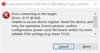
The complete description of the problem in the figure is as follows:Unable to access device register. Reset the device, and retry the operation. If error persists, confirm configuration, power-cycle the board, and/or try more reliable JTAG settings (e.g. lower TCLK). (Emulation package 9.4.0.00129)。The prompts in the console window are as follows:IcePick_C_0: Error connecting to the target: (Error -2131 @ 0x0) .

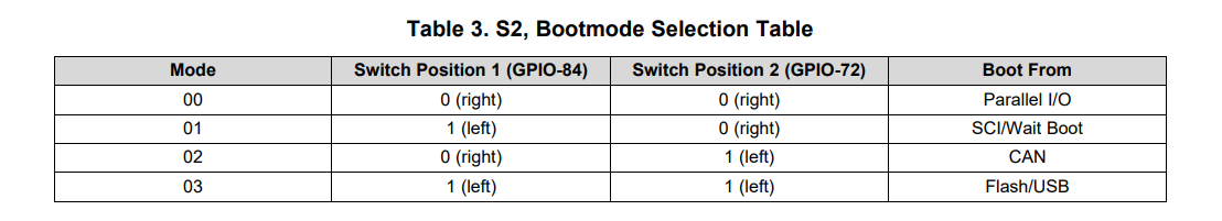
Currently, the status of switches, jumpers, and lights on the control card is as follows: A: SW1, Position 1, and Position 2 are both ON (up); SW1, Position 1 is OFF (upper), and Position 2 is ON (lower); A: J1, connected to PC via Mini USB; LD1, green light; LD3, red light; A: D2, green light.

  • Hi,

    Could you try connecting to the controlCARD without it mounted to the board? You will need to plug in the controlCARD's microUSB connection to supply power. Then you should be able to load the program. If you are still not able to load the program, could you also try putting the controlCARD into Wait Boot mode according to the following table? 

    Best Regards,

    Ben Collier

  • Hi, Ben, thanks a lot for your help!

    I tried the way you said, but it's still the same. The current status is: Micro USB and Mini USB are both connected to the control card, and the control card has been unplugged from the IDDK board. A: SW1, Position 1, and Position 2 are all ON (top. In fact, all four combinations have been tried); SW1, Position 1 (right side) is ON (lower), and Position 2 (left side) is OFF (lower). I checked with a multimeter according to the schematic diagram and confirmed that this status corresponds to the wait boot mode. The status of LEDs is: LD1, green light; LD2, red light; LD3, red light; A: D2, green light.

    I seriously suspect that the XDS 100 v2 on the control card is broken, but I am not sure how to confirm it. If the EMULATOR on the board really breaks down, it seems that this control card cannot be used with the IDDK board because there are no other external emulator or debug probe interfaces on the IDDK board.

  • Hi Stephen,

    The expert is currently out of office, please expect a response back by tomorrow.

  • Hi Stephen,

    Could you please try the 'Test Connection' option in your Target Configuration file in CCS? Please post the output log here, as it will help us determine what is going wrong. 

    Also, do you have access to one of these TI Docking Stations? You shouldn't need one, but it would be helpful in determining if the XDS100V2 is the cause of your problem.

    Best Regards,
    Ben Collier

  • Hi, Benjamin. I have been busy with other work recently and haven't debugged this issue again.

    I don't have a TI Docking Stations. I will buy one if it is necessary. The output log of “test connection” is as follows:

    [Start: Texas Instruments XDS100v2 USB Debug Probe_0]

    Execute the command:

    %ccs_base%/common/uscif/dbgjtag -f %boarddatafile% -rv -o -F inform,logfile=yes -S pathlength -S integrity

    [Result]

    -----[Print the board config pathname(s)]------------------------------------

    C:\Users\SP_TEMP\AppData\Local\TEXASI~1\

        CCS\ccs1010\0\0\BrdDat\testBoard.dat

    -----[Print the reset-command software log-file]-----------------------------

    This utility has selected a 100- or 510-class product.

    This utility will load the adapter 'jioserdesusb.dll'.

    The library build date was 'Jun 25 2021'.

    The library build time was '11:45:30'.

    The library package version is '9.4.0.00129'.

    The library component version is '35.35.0.0'.

    The controller does not use a programmable FPGA.

    The controller has a version number of '4' (0x00000004).

    The controller has an insertion length of '0' (0x00000000).

    This utility will attempt to reset the controller.

    This utility has successfully reset the controller.

    -----[Print the reset-command hardware log-file]-----------------------------

    The scan-path will be reset by toggling the JTAG TRST signal.

    The controller is the FTDI FT2232 with USB interface.

    The link from controller to target is direct (without cable).

    The software is configured for FTDI FT2232 features.

    The controller cannot monitor the value on the EMU[0] pin.

    The controller cannot monitor the value on the EMU[1] pin.

    The controller cannot control the timing on output pins.

    The controller cannot control the timing on input pins.

    The scan-path link-delay has been set to exactly '0' (0x0000).

    -----[The log-file for the JTAG TCLK output generated from the PLL]----------

    There is no hardware for programming the JTAG TCLK frequency.

    -----[Measure the source and frequency of the final JTAG TCLKR input]--------

    There is no hardware for measuring the JTAG TCLK frequency.

    -----[Perform the standard path-length test on the JTAG IR and DR]-----------

    This path-length test uses blocks of 64 32-bit words.

    The test for the JTAG IR instruction path-length failed.

    The JTAG IR instruction scan-path is stuck-at-ones.

    The test for the JTAG DR bypass path-length failed.

    The JTAG DR bypass scan-path is stuck-at-ones.

    ----[Perform the Integrity scan-test on the JTAG IR]------------------------

    This test will use blocks of 64 32-bit words.

    This test will be applied just once.

    Do a test using 0xFFFFFFFF.

    Scan tests: 1, skipped: 0, failed: 0

    Do a test using 0x00000000.

    Test 2 Word 0: scanned out 0x00000000 and scanned in 0xFFFFFFFF.

    Test 2 Word 1: scanned out 0x00000000 and scanned in 0xFFFFFFFF.

    Test 2 Word 2: scanned out 0x00000000 and scanned in 0xFFFFFFFF.

    Test 2 Word 3: scanned out 0x00000000 and scanned in 0xFFFFFFFF.

    Test 2 Word 4: scanned out 0x00000000 and scanned in 0xFFFFFFFF.

    Test 2 Word 5: scanned out 0x00000000 and scanned in 0xFFFFFFFF.

    Test 2 Word 6: scanned out 0x00000000 and scanned in 0xFFFFFFFF.

    Test 2 Word 7: scanned out 0x00000000 and scanned in 0xFFFFFFFF.

    The details of the first 8 errors have been provided.

    The utility will now report only the count of failed tests.

    Scan tests: 2, skipped: 0, failed: 1

    Do a test using 0xFE03E0E2.

    Scan tests: 3, skipped: 0, failed: 2

    Do a test using 0x01FC1F1D.

    Scan tests: 4, skipped: 0, failed: 3

    Do a test using 0x5533CCAA.

    Scan tests: 5, skipped: 0, failed: 4

    Do a test using 0xAACC3355.

    Scan tests: 6, skipped: 0, failed: 5

    Some of the values were corrupted - 83.3 percent.

    The JTAG IR Integrity scan-test has failed.

    -----[Perform the Integrity scan-test on the JTAG DR]------------------------

    This test will use blocks of 64 32-bit words.

    This test will be applied just once.

    Do a test using 0xFFFFFFFF.

    Scan tests: 1, skipped: 0, failed: 0

    Do a test using 0x00000000.

    Test 2 Word 0: scanned out 0x00000000 and scanned in 0xFFFFFFFF.

    Test 2 Word 1: scanned out 0x00000000 and scanned in 0xFFFFFFFF.

    Test 2 Word 2: scanned out 0x00000000 and scanned in 0xFFFFFFFF.

    Test 2 Word 3: scanned out 0x00000000 and scanned in 0xFFFFFFFF.

    Test 2 Word 4: scanned out 0x00000000 and scanned in 0xFFFFFFFF.

    Test 2 Word 5: scanned out 0x00000000 and scanned in 0xFFFFFFFF.

    Test 2 Word 6: scanned out 0x00000000 and scanned in 0xFFFFFFFF.

    Test 2 Word 7: scanned out 0x00000000 and scanned in 0xFFFFFFFF.

    The details of the first 8 errors have been provided.

    The utility will now report only the count of failed tests.

    Scan tests: 2, skipped: 0, failed: 1

    Do a test using 0xFE03E0E2.

    Scan tests: 3, skipped: 0, failed: 2

    Do a test using 0x01FC1F1D.

    Scan tests: 4, skipped: 0, failed: 3

    Do a test using 0x5533CCAA.

    Scan tests: 5, skipped: 0, failed: 4

    Do a test using 0xAACC3355.

    Scan tests: 6, skipped: 0, failed: 5

    Some of the values were corrupted - 83.3 percent.


    The JTAG DR Integrity scan-test has failed.


    [End: Texas Instruments XDS100v2 USB Debug Probe_0]

  • Hi Stephen,

    From this error message, it is possible that the problem is with the C2000 device itself. It is also possible that there is something wrong with the XDS100v2, but that seems less likely. 

    Which control card are you using? Most control cards have a switch to select between using the on-board JTAG debug probe or using an external JTAG debug probe and the docking station. Is it possible that this switch is set to be using the external JTAG debug probe? 

    Best Regards,

    Ben Collier 

  • Hi, Benjamin. The controlcard is "TMDSCNCDF28379D". 

    I noticed that the control card needs to select the jtag debug probe and confirmed that I have chosen the on board jtag debug probe. The status of switch A: SW1 is as previously described in the problem description: Position 1, and Position 2 are both ON (up), consistent with the guidance in the SPRUI76 document.

    At present, I am using a TMDSCNCD28388D control card for debugging and can connect to IDDK EVM Board normally.

  • Hi Stephen,

    I think the next step in debugging would be to try to connect with a TI Docking station and a standalone JTAG Debug Probe, but I am worried that the C2000 part on your controlCARD is damaged. Have you ever been able to connect to this controlCARD before? 

    Best Regards,

    Ben Collier