This thread has been locked.

If you have a related question, please click the "Ask a related question" button in the top right corner. The newly created question will be automatically linked to this question.

TMS320F280040-Q1: PWM trip-zone timing

Part Number: TMS320F280040-Q1

Hi, 

Trip-Zone input timing 

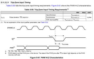
What does Pulse duration mean in following PWM Hi-Z Characteristics in datasheet?

Is the timing required to trigger the fault condition on the ePWM module?

If yes, the waveform is not understandable.

In the waveform below, It looks likes the PWM is forced Hi-Z before satisfying the pulse width.

Also, the delay time starts when TZ input goes low.

  • Hi SY,

    The delay time of td(TZ-PWM) is described in the "ePWM Switching Characteristics" table. In this diagram, the delay time starts on the first rising edge of EPWMCLK when TZ is low. The trip zone input timing requirements table describes the minimum pulse width to guarantee the trip will be recognized regardless of when TZ goes low. A shorter pulse width may still trigger a trip depending on the timing of when the trip signal goes low but won't trigger a trip in all cases, which is why the data sheet indicates a pulse-width requirement for the trip to function as expected 100% of the time.