Other Parts Discussed in Thread: DRV8320, MOTORWARE, , C2000WARE-MOTORCONTROL-SDK, C2000WARE, SFRA, DRV8323
Hello,
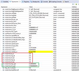
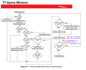
After getting LAB is07 to run motor ID steps via ISR vectored switch case reacting to (user.c) wait times, RS impedance is very wrong even via is05 motor ID via custom inverter on booster headers J5-J6. The motor runs easily 10KRPM via same custom inverter by user settings derived by DRV8320RS SPI driver chip. However, RoverL_rps is sometimes spot on (516.6 rps) but RS impedance is very low values. Also started to provision MCSDK for BSXL-DRV8320RS via x49c launch pad but there are many places (hal.c) and other files the projects active configuration touches. Like to keep 3 ADC's in MCSDK via x49c, is that possible without too much effort?
Are the RS impedance and RoverL_rps values linked to the design of the BSXL_DRV83xx chip gate driver switching characteristics?
Setting the controller for 1-3 ADC ISR ticks sometimes the very first values are correct but over default wait times RS and RoverL_rps both values get very low. For example, motor impedance of 0.316983044 changes to (0.0012000) and RoverL_rps (517.6) more often lands at 6.1. How to improve these measured values via custom inverter? What determines motor RS impedance other than RoverL_rps injecting current into phase coils?
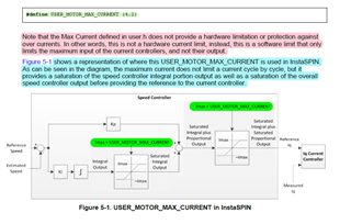
Secondly phase current jumps from USER_MOTOR_RES_EST_CURRENT = 0.35 to ADC 14 amps during first part of ramp up 60Hz and USER_MOTOR_IND_EST_CURRENT_A = -0.315. The HID monitors the ADC current so user can force a panic stop at any point in the ID process, double tap stop button. USER_MOTOR_MAX_CURRENT_A = 0.4 amps and same 0.4 amps (below calls) controller (maxCurrent_A) shows in debug pause. So it does not seem to be a suspect for high current in ramp up. Yet this value (0.4) is supposed to constrain the PWM duty cycle current but is not doing so in is07 motor ID.
CTRL_setSpeed_outMax_A(handle,pUserParams->maxCurrent_A);
CTRL_setSpeed_outMin_A(handle,-pUserParams->maxCurrent_A);
Can the trajectory delta macro (USER_ISR_FREQ_Hz) lead to such high current during ramp up? So the RoverL_rps has 200Hz frequency and motor shaft does not spin going into RS impedance.
TRAJ_setMaxDelta(trajHandle_spd, (motorVars.accelerationStart_Hzps / USER_ISR_FREQ_Hz));
6.6.4 CTRL_State_OnLine and EST_State_Rs
This state of the identification process performs the identification of the stator resistance (Figure 6-14).
A DC current is injected into the D-axis with the amplitude defined in user.h as follows:
#define USER_MOTOR_RES_EST_CURRENT (1.0)
Note that this current is the same definition used for RoverL state, although RoverL uses half of this value, and the Rs state uses the full value in the definition. The injected current should be high enough to generate a significant measurement in the ADC converter, and at the same time low enough to avoid motor overheating. Typically, 10% to 20% of the rated current of the motor is enough to produce an accurate estimation of the stator resistance. The time interval for this state is set by three-time values in user.c, as follows:
pUserParams->RsWaitTime[EST_Rs_State_RampUp] = (uint_least32_t)(1.0*USER_EST_FREQ_Hz);
pUserParams->RsWaitTime[EST_Rs_State_Coarse] = (uint_least32_t)(2.0*USER_EST_FREQ_Hz);
pUserParams->RsWaitTime[EST_Rs_State_Fine] = (uint_least32_t)(4.0*USER_EST_FREQ_Hz);
By default, the entire process of identifying the stator resistance, Rs, takes 7 seconds.
BTW: CCS Advice tab suggested to change int32_t to float32_t in wait times since some wait values had floating fractional parts. Though I wonder if the estimator state machine ignores the fractional parts.


