This thread has been locked.

If you have a related question, please click the "Ask a related question" button in the top right corner. The newly created question will be automatically linked to this question.

TMS320F28377S: TMS320F28377S

Part Number: TMS320F28377S
Other Parts Discussed in Thread: C2000WARE

Hello, 

My question is in two parts viz:

No. 1:  I have 8 HR ePWM to control a converter. All of them have the same frequency and duty cycle but different phase shifts. I need one more PWM (call it ePWM 9A) to operate at 100% duty cycle. Can any of the normal PWMs 10 - 16 provide 100% duty cycle as pp 1786 of the Tech. Ref. Manual says that their is limitation to the duty cycle (12.5% - 87.5%)?

No. 2: If No. 1 is possible, how do I configure the ePWM9A to operate on 100% duty cycle having configured the first eight PWMs (HR ePWM) to operate at 50% duty cycle?

No. 3: I need to turn on ePWM 9A when certain condition is met. I am not savy in this regard (pardon me) but I'll explain this using the analogy below

        if (A >B) {

                        Do not turn on ePWM 9A                   

                        All the 8 HR ePWM are swiching

                   }

         else {

                       Turn on ePWM 9A;

                       All the 8 ePWM are still switching;

                 {

Therefore, how do I disable and enable ePWM 9A? 

The below looks like a solution from previous answered questions:

"

Disable the PWM where x is the pwm No.

EALLOW;
EpwmxRegs.TZFRC.bit.OST = 1;
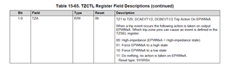
EpwmxRegs.TZCTL.bit.TZA = 0x02; // fOR FORCE low
EpwmxRegs.TZCTL.bit.TZB = 0x02; //fOR fORCE loW
EDIS;

// Enable the PWM where x is the pwm No.


EALLOW;
EpwmxRegs.TZCTL.bit.OST = 0x01; // fOR FORCE low
EpwmxRegs.TZCTL.bit.OST = 0x01; //fOR fORCE loW
EDIS;

"

But the comment for both anable and disable pointed to force low. Please advise.

Regards,

Olutayo.

  • Hi Olutayo,

    No1: For ePWM without HR yes you can have 100% duty cycle.

    No2/3: 100% duty cycle  can be achieved by setting the outputs at ePWM9A/B to constant high by using a trip event.

    The TZFRC.bit.OST  will force a software trip event that will force the outputs to be whatever you configure the TZCTL.bit.TZA /B to be. TZCTL.bit.TZA will configure what happens to your ePWMA output. to set the outputs low or high you can refer to this within the register TRM table

    If 

    EpwmxRegs.TZCTL.bit.OST = 0x01;

    then the outputs are set to go constant high state. (turning the pwm to 100% duty cycle)

    if EpwmxRegs.TZCTL.bit.OST = 0x02;

    outputs are constant low 

    Hope this helps,

    Ryan Ma

  • Hi, 

    Thank you for your advice. I was able to achieve this on ePWM 1-8.  My current challenge is that I could not have an output for my ePWM9 (&10).  So I was unable to test your recommendation on ePWM9 (&10). I know it will work should there be an output. Could you please help me have a look at my attched code if there are reasons why I couldn't get any PWM output.

    I have tried studying the code examples from TMS320F28377S and also looked at both datasheet and TRM. Please help.

    Regards,

     //  >>>>>>>>>>>>>>>>>>>>>>>>>>>>>>>>>>

    #include <F28x_Project.h>

    void InitEPwm9_PRJ1155(void);

    void InitEPwm10_PRJ1155(void);

    void main1(void)

       {

           InitSysCtrl();                        // Step 1. Initialize System Control: PLL, WatchDog, enable Peripheral Clocks


           InitGpio();                           // Initialize GPIO to default


           CpuSysRegs.PCLKCR2.bit.EPWM9 = 1;     // Enable PWM9

           CpuSysRegs.PCLKCR2.bit.EPWM10 = 1;    // // Enable PWM10


           InitEPwm9Gpio();                      // Init GPIO pins for ePWM9

           InitEPwm10Gpio();                     // Init GPIO pins for ePWM10


           DINT;                                 // Clear all interrupts and initialize PIE vector table: Disable CPU interrupts

           InitPieCtrl();                        // Initialize the PIE control registers to their default state. The default state is all PIE interrupts disabled and flags are cleared.


           // Disable CPU interrupts and clear all CPU interrupt flags:

           IER = 0x0000;

           IFR = 0x0000;


           // Initialize the PIE vector table with pointers to the shell Interrupt Service Routines (ISR).

           InitPieVectTable();


           // Initialize the ePWM

           EALLOW;

           CpuSysRegs.PCLKCR0.bit.TBCLKSYNC = 0;

           EDIS;


           InitEPwm9_PRJ1155();

           InitEPwm10_PRJ1155();


           EALLOW;

           CpuSysRegs.PCLKCR0.bit.TBCLKSYNC = 1;

           EDIS;


           // Enable CPU INT3 which is connected to EPWM9-10 INT:

           IER |= M_INT3;


           // Enable EPWM INTn in the PIE: Group 3 interrupt 9-10

           PieCtrlRegs.PIEIER3.bit.INTx9 = 1;

           PieCtrlRegs.PIEIER3.bit.INTx10 = 1;


           EINT;  // Enable Global interrupt INTM

           ERTM;  // Enable Global realtime interrupt DBGM


           for(;;)

                     {

                         asm ("          NOP");

                     }

       }


     void InitEPwm9_PRJ1155()


     {


          EPwm9Regs.TBPRD = 999; // Period = 1000 TBCLK counts

          EPwm9Regs.TBPHS.bit.TBPHS = 0; // Phase = 0/1000 * 360 = 0 deg

          EPwm9Regs.TBCTR = 0x0000;                     // Clear counter


          EPwm9Regs.TBCTL.bit.CTRMODE = 2; // Symmetrical mode

          EPwm9Regs.TBCTL.bit.PHSEN = 1; // Slave module

          EPwm9Regs.TBCTL.bit.PHSDIR = 1; // Count DOWN on sync (=120 deg)


          EPwm9Regs.TBCTL.bit.HSPCLKDIV = 0;       // Clock ratio to SYSCLKOUT

          EPwm9Regs.TBCTL.bit.CLKDIV = 0;


          EPwm9Regs.TBCTL.bit.PRDLD = TB_SHADOW;

          EPwm9Regs.TBCTL.bit.SYNCOSEL = TB_SYNC_IN; // sync flow-through

          EPwm9Regs.CMPCTL.bit.SHDWAMODE = CC_SHADOW;

          EPwm9Regs.CMPCTL.bit.SHDWBMODE = CC_SHADOW;

          EPwm9Regs.CMPCTL.bit.LOADAMODE = CC_CTR_ZERO; // load on CTR=Zero

          EPwm9Regs.CMPCTL.bit.LOADBMODE = CC_CTR_ZERO; // load on CTR=Zero

          EPwm9Regs.AQCTLA.bit.CAU = AQ_SET; // set actions for EPWM2A

          EPwm9Regs.AQCTLA.bit.CAD = AQ_CLEAR;

          EPwm9Regs.DBCTL.bit.IN_MODE = DBA_ALL; // enable Dead-band module

          EPwm9Regs.DBCTL.bit.POLSEL = DB_ACTV_HIC; // Active Hi Complementary

          EPwm9Regs.DBFED.bit.DBFED = 40; // Not critical as only high-side is used

          EPwm9Regs.DBRED.bit.DBRED = 40; // Not critical as only high-side is used

          EPwm9Regs.CMPA.bit.CMPA = 540; // adjust duty for output EPWM9A

          EPwm9Regs.CMPB.bit.CMPB= 500; // adjust duty for output EPWM9A

          //EPwm10Regs.TZCTL.bit.TZA = TZ_FORCE_HI;         // When trip force low

          // EPwm10Regs.TZCTL.bit.TZB = TZ_FORCE_HI;         // When trip force low

     }

      // EPWM Module 10 config


     void InitEPwm10_PRJ1155(void)

     {

           EPwm10Regs.TBPRD = 999; // Period = 1000 TBCLK counts

           EPwm10Regs.TBPHS.bit.TBPHS = 0; // Phase = 0/1000 * 360 = 0 deg

           EPwm10Regs.TBCTR = 0x0000;                     // Clear counter


           EPwm10Regs.TBCTL.bit.CTRMODE = 2; // Symmetrical mode

           EPwm10Regs.TBCTL.bit.PHSEN = 1; // Slave module

           EPwm10Regs.TBCTL.bit.PHSDIR = 1; // Count DOWN on sync (=120 deg)


           EPwm10Regs.TBCTL.bit.HSPCLKDIV = 0;       // Clock ratio to SYSCLKOUT

           EPwm10Regs.TBCTL.bit.CLKDIV = 0;


           EPwm10Regs.TBCTL.bit.PRDLD = TB_SHADOW;

           EPwm10Regs.TBCTL.bit.SYNCOSEL = TB_SYNC_IN; // sync flow-through

           EPwm10Regs.CMPCTL.bit.SHDWAMODE = CC_SHADOW;

           EPwm10Regs.CMPCTL.bit.SHDWBMODE = CC_SHADOW;

           EPwm10Regs.CMPCTL.bit.LOADAMODE = CC_CTR_ZERO; // load on CTR=Zero

           EPwm10Regs.CMPCTL.bit.LOADBMODE = CC_CTR_ZERO; // load on CTR=Zero

           EPwm10Regs.AQCTLA.bit.CAU = AQ_SET; // set actions for EPWM2A

           EPwm10Regs.AQCTLA.bit.CAD = AQ_CLEAR;

           EPwm10Regs.DBCTL.bit.IN_MODE = DBA_ALL; // enable Dead-band module

           EPwm10Regs.DBCTL.bit.POLSEL = DB_ACTV_HIC; // Active Hi Complementary

           EPwm10Regs.DBFED.bit.DBFED = 40; // Not critical as only high-side is used

           EPwm10Regs.DBRED.bit.DBRED = 40; // Not critical as only high-side is used

           EPwm10Regs.CMPA.bit.CMPA = 540; // adjust duty for output EPWM9A

           EPwm10Regs.CMPB.bit.CMPB= 500; // adjust duty for output EPWM9A

           // EPwm10Regs.TZCTL.bit.TZA = TZ_FORCE_HI;         // When trip force low

           // EPwm10Regs.TZCTL.bit.TZB = TZ_FORCE_HI;         // When trip force low

     }

    // >>>>>>>>>>

  • In your init I would set up your TZCTL.bit.TZA / TZB and you have to wrap it around with EALLOW; and EDIS; since they are protected registers

    EALLOW;

     EPwm10Regs.TZCTL.bit.TZA = TZ_FORCE_HI;         // When trip force low

      EPwm10Regs.TZCTL.bit.TZB = TZ_FORCE_HI;         // When trip force low

    EDIS;

    Then when you want to software force the outputs to go high or low, you can write to the 

     Epwm10Regs.TZFRC.bit.OST = 1;

    In order for the outputs to resume to their original settings based on their action qualifier you can clear the OST flag with

    TZCLR[OST] = 1;

    Best,

    Ryan Ma

  • Hi,

    Thank you for your advice. 

    However, the thread is now about the fact that I could not get the conventional PWM output. Is this what your last advice addressing - apologies if I caused a bit of confusion? If yes, I'll try it out. Otherwise, I need your advice on getting the custom PWM in the first instance.

    Regards

  • Sorry if I misunderstood, you're not seeing any PWM output at the pins for epwm9 / 10? did you configure your pins correctly for these modules?

    Best,

    Ryan Ma

  • I have followed the configuration procedure and came up with the code I sent earlier but no output. Will be happy if you can help have a look.

    Regards.

  • Hi Olutayo,

    Could I also see how you configured your GPIO?

    Your PWM initialization looks to be fine. 

  • void InitEPwm9Gpio(void)
    {
    EALLOW;

    GpioCtrlRegs.GPAPUD.bit.GPIO16 = 1; // Disable pull-up on GPIO16 (EPWM9A)
    GpioCtrlRegs.GPAPUD.bit.GPIO17 = 1; // Disable pull-up on GPIO17 (EPWM9B)


    GpioCtrlRegs.GPAGMUX2.bit.GPIO16 = 1; // Configure GPIO16 as EPWM9A
    GpioCtrlRegs.GPAGMUX2.bit.GPIO17 = 1; // Configure GPIO17 as EPWM9B

    EDIS;
    }


    void InitEPwm10Gpio(void)
    {
    EALLOW;

    GpioCtrlRegs.GPAPUD.bit.GPIO18 = 1; // Disable pull-up on GPIO163 (EPWM10A)
    GpioCtrlRegs.GPAPUD.bit.GPIO19 = 1; // Disable pull-up on GPIO164 (EPWM10B)


    GpioCtrlRegs.GPAGMUX2.bit.GPIO18 = 1; // Configure GPIO163 as EPWM10A
    GpioCtrlRegs.GPAGMUX2.bit.GPIO19 = 1; // Configure GPIO164 as EPWM10B

    EDIS;
    }

  • Hi Olutayo,

    Could you try this instead?

    void InitEPwm9Gpio(void)
    {
        EALLOW;
        //
        // Disable internal pull-up for the selected output pins
        // for reduced power consumption
        // Pull-ups can be enabled or disabled by the user.
        // This will enable the pullups for the specified pins.
        // Comment out other unwanted lines.
        //
        GpioCtrlRegs.GPFPUD.bit.GPIO161 = 1;    // Disable pull-up on GPIO161 (EPWM9A)
        GpioCtrlRegs.GPFPUD.bit.GPIO162 = 1;    // Disable pull-up on GPIO162 (EPWM9B)
    
        //
        // Configure EPWM-6 pins using GPIO regs
        // This specifies which of the possible GPIO pins will be EPWM6 functional
        // pins.
        // Comment out other unwanted lines.
        //
        GpioCtrlRegs.GPFMUX1.bit.GPIO161 = 1;   // Configure GPIO161 as EPWM9A
        GpioCtrlRegs.GPFMUX1.bit.GPIO162 = 1;   // Configure GPIO162 as EPWM9B
        // GpioCtrlRegs.GPAPUD.bit.GPIO16 = 1; // Disable pull-up on GPIO16 (EPWM9A)
        // GpioCtrlRegs.GPAPUD.bit.GPIO17 = 1; // Disable pull-up on GPIO17 (EPWM9B)
        
        
        // GpioCtrlRegs.GPAMUX2.bit.GPIO16 = 1; // Configure GPIO16 as EPWM9A
        // GpioCtrlRegs.GPAMUX2.bit.GPIO17 = 1; // Configure GPIO17 as EPWM9B
        EDIS;
    }
    
    //
    // InitEPwm10Gpio - Initialize EPWM10 GPIOs
    //
    void InitEPwm10Gpio(void)
    {
        EALLOW;
        //
        // Disable internal pull-up for the selected output pins
        // for reduced power consumption
        // Pull-ups can be enabled or disabled by the user.
        // This will enable the pullups for the specified pins.
        // Comment out other unwanted lines.
        //
        GpioCtrlRegs.GPFPUD.bit.GPIO163 = 1;    // Disable pull-up on GPIO163 (EPWM10A)
        GpioCtrlRegs.GPFPUD.bit.GPIO164 = 1;    // Disable pull-up on GPIO164 (EPWM10B)
    
        //
        // Configure EPWM-6 pins using GPIO regs
        // This specifies which of the possible GPIO pins will be EPWM6 functional
        // pins.
        // Comment out other unwanted lines.
        //
        GpioCtrlRegs.GPFMUX1.bit.GPIO163 = 1;   // Configure GPIO163 as EPWM10A
        GpioCtrlRegs.GPFMUX1.bit.GPIO164 = 1;   // Configure GPIO164 as EPWM10B
        //GpioCtrlRegs.GPAPUD.bit.GPIO18 = 1; // Disable pull-up on GPIO163 (EPWM10A)
        //GpioCtrlRegs.GPAPUD.bit.GPIO19 = 1; // Disable pull-up on GPIO164 (EPWM10B)
    
        //GpioCtrlRegs.GPAMUX2.bit.GPIO18 = 1; // Configure GPIO163 as EPWM10A
        //GpioCtrlRegs.GPAMUX2.bit.GPIO19 = 1; // Configure GPIO164 as EPWM10B
        EDIS;
    }

  • Hello Ryan,

    Thank you for the advice.

    Am I missing something? The GPIOs for F28377SPTP do not have number allocations such as GPIOs161 - 164 but the there pins numbered 161 - 164. In any case, I aready allocated pins 160, 161, 162, 163, 164, 165, 166, 167, 1, 2, 4, 5, 6, 7, 18, 19   (corresponding to GPIOs 0-7, 10, 11, & 12-18) to ePWM1-8.  so I previously allocated pins  8, 9, 10, 12 (corresponding to GPIOs 16, 17, 18 & 19) to ePWM9&10.

    Again, as seen in the TRM, MUX1 and MUX2 are for (GPIO0 to 15) & (GPIO16 to 31) respectively.  Please correct me if my analysis is wrong.

    Regards

  • Hi Olutayo,

    I am also referencing an example from our C2000WARE SDK that shows how to setup the GPIO for pwm1-12.

    MUX1 means GPIO0-15, MUX2 is GPIO 16-31. That is correct.

    The Group letter corresponds to the GPIOs.

    MUX1 and MUX2 will split these group into the first half going to MUX1 and the second half going to MUX2 (if there are 32 total gpio for that port). That is why you see for GPIO161:

    GpioCtrlRegs.GPFMUX1.bit.GPIO161 = 1;

                                ^--- "F" means Port F and I can select GPIO160 - 168

    However there are two configurations for GPIO you have to consider now since you are using a different peripheral group.

    Since you are wanting to use GPIO 16, this belongs in Port A (GPIO0-31).

    Since we want to use the peripheral EPWM9A (O) this belongs in peripheral group 01b of row GPyGMUXnGPIOz NOT in group 00b

    Then you can configure which peripheral from this group you want with GPyMUXnGPIOz.

    So in bitfield the correct way to get an output from this pin when wanting a PWM peripheral output would be this:

         GpioCtrlRegs.GPAPUD.bit.GPIO16 = 1;    // Disable pull-up on GPIO16 (EPWM9A)
        GpioCtrlRegs.GPAPUD.bit.GPIO16 = 1;    // Disable pull-up on GPIO16 (EPWM9B)
        GpioCtrlRegs.GPAGMUX2.bit.GPIO16 = 0x1; // configure the peripheral group (01b)
        GpioCtrlRegs.GPAMUX2.bit.GPIO16 = 0x1; // configure the peripheral (01) (EPWM9A)
        GpioCtrlRegs.GPAGMUX2.bit.GPIO17 = 0x1; 
        GpioCtrlRegs.GPAMUX2.bit.GPIO17 = 0x1;

  • Hi Ryan,

    Thank you for your advice.

    This was the initial configuration from which I was not getting any output. See our previous conversation or have a look at the screeshot of our conversation below:

  • Hi Olutayo,

    Yes you have that correct, but you need also this line after it.

    GpioCtrlRegs.GPAMUX2.bit.GPIO16 = 0x1; // configure the peripheral (01) (EPWM9A)

  • Hi Ryan,

    Do you mean I should repeat the line? Did you observe the line was included as higlighted in the screenshot below?

    If it needs to be included please let me know.

    Regards

  • Hi Olutayo,

    Yes You need to include both these lines. Keep note that these lines are different. One configures the peripheral group the other configures which peripheral within that group.

    GpioCtrlRegs.GPAGMUX2.bit.GPIO16 = 0x1; // configure the peripheral group (01b)

    GpioCtrlRegs.GPAMUX2.bit.GPIO16 = 0x1; // configure the peripheral (01) (EPWM9A)

  • Thank you Ryan. ePWM9B has an output now but 9B has none. 

    Could the interrupt be the cause? May I check if the interrupt is correctly set:

    IER |= M_INT3;

    // Enable EPWM INTn in the PIE: Group 3 interrupt 9-10

    PieCtrlRegs.PIEIER3.bit.INTx9 = 1;
    PieCtrlRegs.PIEIER3.bit.INTx10 = 1;

    EINT; // Enable Global interrupt INTM

    ERTM; // Enable Global realtime interrupt DBGM.

    Can you please send me the reference here: 

    Regards

  • Interrupt should not be the cause for initialization of the GPIOs / ePWMs. Your interrupt init looks good.

    I showed you for EPWM9A/9B, it will be similar for 10A/B.

    Here is the example I can refer you to found here: C:\ti\c2000\C2000Ware_4_03_00_00\device_support\f2837xs\examples\cpu1\epwm_up_aq

    Best,

    Ryan Ma