


Other Parts Discussed in Thread: TIDM-02009, PMP23126
Hi Gus,
I loaded my PCMC software to my PSFB CDR board. I drive switches for TR-LEAD topology, QD ends power transfer interval. I investigated the software of TIDM-02009, PMP23126.
I'm testing the only inner loop performance so I changed the MAXREF value via UART and change the peak current set value.
I obtained following unequal current waveforms on Lext. By the way, I use diode bridge to rectify the output of CT current.
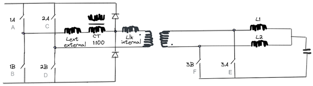
Schematic is as below.
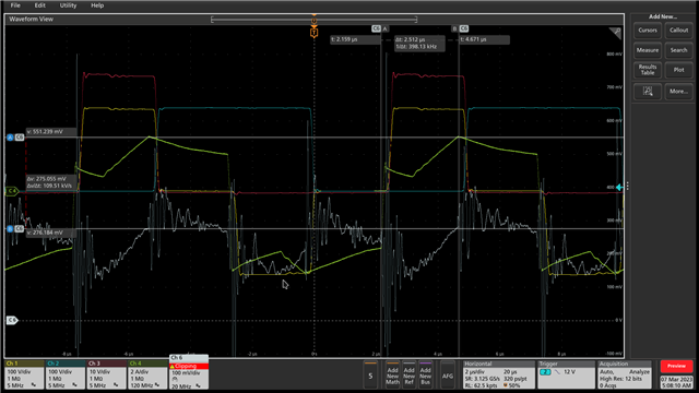
Oscilloscope colours is as below:
GREEN: Current on CT, GRAY: ADC Signal - Output of CT,
YELLOW: Primary Voltage of Transformer, BLUE: 2B VDS,
RED: 3A VDS
Waveform#1 is as below.
Vin=250 Iin=1.1 Vout=7.9 Iout=31.35, Load is, CR mode=0,25ohm
Waveform#2 is as below.
Vin=250 Iin=2.5 Vout=12.09 Iout=48.12, CR mode=0,25ohm

Waveform #3 is as below, I removed clamping diodes and get following waveforms.
Vin=250V, Iin=1.8, Vout=10.09, Iout=40,CR mode=0,25ohm

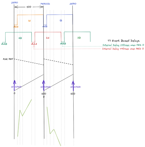
PWM8 generates SYNCPER signal at all ZERO and I use PWM1 and PWM2 to drive power switches.
void SYNC_init(void)
{
    SysCtl_setSyncOutputConfig(SYSCTL_SYNC_OUT_SRC_EPWM1SYNCOUT);
    //
    // For EPWM1, the sync input is: SYSCTL_SYNC_IN_SRC_EXTSYNCIN1
    //
    SysCtl_setSyncInputConfig(SYSCTL_SYNC_IN_EPWM4, SYSCTL_SYNC_IN_SRC_EPWM1SYNCOUT);
    SysCtl_setSyncInputConfig(SYSCTL_SYNC_IN_EPWM7, SYSCTL_SYNC_IN_SRC_EPWM1SYNCOUT);

}
void InitHRPWM1(void)
{
    EPWM_setPeriodLoadMode(EPWM1_BASE, EPWM_PERIOD_SHADOW_LOAD);

    // Time-Base Submodule Configurations
    EPWM_setClockPrescaler(EPWM1_BASE,EPWM_CLOCK_DIVIDER_1,EPWM_HSCLOCK_DIVIDER_1);
    EPWM_setTimeBasePeriod(EPWM1_BASE, PeriodValue);
    EPWM_setTimeBaseCounter(EPWM1_BASE, 0U);
    EPWM_setTimeBaseCounterMode(EPWM1_BASE, EPWM_COUNTER_MODE_UP_DOWN);

    //
    // Phase Configuration and Set
    // Configure PWM base1 as master
    // SetPhaseShift as zero!
    //
    EPWM_disablePhaseShiftLoad(EPWM1_BASE);
    EPWM_setPhaseShift(EPWM1_BASE, 0U);
    EPWM_setSyncOutPulseMode(EPWM1_BASE, EPWM_SYNC_OUT_PULSE_ON_COUNTER_ZERO);
}
void InitHRPWM2(void)
{
    // MISC. Period Load Mode
    EPWM_setPeriodLoadMode(EPWM2_BASE, EPWM_PERIOD_SHADOW_LOAD);

    // Time-Base Submodule Configurations
    EPWM_setClockPrescaler(EPWM2_BASE,EPWM_CLOCK_DIVIDER_1,EPWM_HSCLOCK_DIVIDER_1);
    EPWM_setTimeBasePeriod(EPWM2_BASE, PeriodValue);
    EPWM_setTimeBaseCounter(EPWM2_BASE, 0U);
    EPWM_setTimeBaseCounterMode(EPWM2_BASE, EPWM_COUNTER_MODE_UP_DOWN);

    //
    // Phase Configuration and Set
    // Configure PWM base2 as slave
    // SetPhaseShift = Value*TBCLK = Value*10nsec
    //
    EPWM_enablePhaseShiftLoad(EPWM2_BASE);
    EPWM_setSyncOutPulseMode(EPWM2_BASE, EPWM_SYNC_OUT_PULSE_ON_EPWMxSYNCIN);

    EPWM_setPhaseShift(EPWM2_BASE, 2); // Value*TBCLKs Phase-Shift is Set
    EPWM_setCountModeAfterSync(EPWM2_BASE, EPWM_COUNT_MODE_UP_AFTER_SYNC);
}
    void InitHRPWM8(void)
{
    EPWM_setPeriodLoadMode(EPWM8_BASE, EPWM_PERIOD_SHADOW_LOAD);
    // Time-Base Submodule Configurations
    EPWM_setClockPrescaler(EPWM8_BASE,EPWM_CLOCK_DIVIDER_1,EPWM_HSCLOCK_DIVIDER_1);
    EPWM_setTimeBasePeriod(EPWM8_BASE, PeriodValue -1);
    EPWM_setTimeBaseCounter(EPWM8_BASE, 0);
    EPWM_setTimeBaseCounterMode(EPWM8_BASE, EPWM_COUNTER_MODE_UP);

    //
    // Phase Configuration and Set
    // Configure PWM base3 as slave
    // SetPhaseShift = Value*TBCLK = Value*10nsec
    EPWM_enablePhaseShiftLoad(EPWM8_BASE);
    EPWM_setPhaseShift(EPWM8_BASE, 2); // Will be clarified later on!
    EPWM_setSyncOutPulseMode(EPWM8_BASE, EPWM_SYNC_OUT_PULSE_ON_EPWMxSYNCIN);
    EPWM_setCountModeAfterSync(EPWM8_BASE, EPWM_COUNT_MODE_UP_AFTER_SYNC);

    HRPWM_setSyncPulseSource(EPWM8_BASE,HRPWM_PWMSYNC_SOURCE_ZERO);
}
void PSFB_HAL_initCmpssPCMC(void)
{
    CMPSS_configHighComparator(CMPSS5_BASE,CMPSS_INSRC_DAC);
    ASysCtl_selectCMPHPMux(ASYSCTL_CMPHPMUX_SELECT_5,0);
    CMPSS_configDAC(CMPSS5_BASE, CMPSS_DACREF_VDDA |CMPSS_DACVAL_PWMSYNC | CMPSS_DACSRC_RAMP);
    CMPSS_configRamp(CMPSS5_BASE,0,0,0U,8U,true);
    CMPSS_initFilterHigh(CMPSS5_BASE);
    CMPSS_configOutputsHigh(CMPSS5_BASE,
                CMPSS_TRIP_ASYNC_COMP | CMPSS_TRIPOUT_ASYNC_COMP);

    // Clear the latched comparator events
    CMPSS_clearFilterLatchHigh(CMPSS5_BASE);
    CMPSS_clearFilterLatchLow(CMPSS5_BASE);

    // Enables the CMPSS module.
    CMPSS_enableModule(CMPSS5_BASE);
    DEVICE_DELAY_US(500);
Could you please help on why I got unequal primary peak current levels on ADC voltage?
Could you please investigate my related software lines?


