This thread has been locked.

If you have a related question, please click the "Ask a related question" button in the top right corner. The newly created question will be automatically linked to this question.

TMS320F280049: CAN bus error and internal pull up

Part Number: TMS320F280049
Other Parts Discussed in Thread: SN65HVD230

Hi Experts,

Seeking your assistance please:

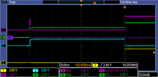
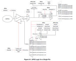
We observe an error on the CAN Bus after starting the µC, there is an dominate bit of 120ms my first question is: are there different pullup resistors in the µC depending of the selected mode? example pin initialized as GPIO the pullup is different to pin initialized as CAN TX/RX?

One more thing, With the first prototype we had no problems, µC and SN65HVD230 are connected directly.


At the seconde prototype we had to add a galvanically isolation, see picture. now it looks, that the internal pullup of the µC can be different as mentioned before In seems that the CAN TX is high but the ADUM1201 brings the voltage down, but after setting the bit rate of the internal controller the pin is stable high.

Regards,
Archie A.

  • are there different pullup resistors in the µC depending of the selected mode?

    No. The pull-up circuitry is one and it is the same.

    but after setting the bit rate of the internal controller the pin is stable high.

    Setting the bit-rate has no effect for the phenomenon you are observing. Whether or not the internal pull-up is active may have an effect. At reset, the pins come up as inputs with the internal PU enabled. 

    The image of your circuit is blurred, so I am unable to discern any details from it.

  • Hi Hareesh,

    Good Day. I am Ray Vincent, a colleague of Archie and our customer has some clarification with your reply. Please see below for your reference.

    In this picture, yellow is CAN TX, green is the µC Power, and magenta is CAN Differential behind the CAN Transceiver.

    You said: "Setting the bit-rate has no effect on the phenomenon you are observing. Whether or not the internal pull-up is active may have an effect. At reset, the pins come up as inputs with the internal PU enabled."

    ---> Customer Concern: How can the CAN TX remain 120ms low, if the PIN is internal pull-up enabled? because it is low, it creates a dominant bit at the CAN bus, which results in a bus off for other bus members.

    ---> Another Customer Concern: After 120ms the PIN is high and everything is fine, I have had no changes during this time but you wrote: "The pull-up circuitry is one and it is the same". How can you explain the change from low to high if the pull-up is always the same?

    Please advise. Thank you very much.

    Best Regards,

    Ray Vincent

  • Ray,

    ---> Customer Concern: How can the CAN TX remain 120ms low, if the PIN is internal pull-up enabled? because it is low, it creates a dominant bit at the CAN bus, which results in a bus off for other bus members.

    The only way this is possible is if the pin is being driven low (either by C2000 or another device connected to the CAN-TX pin on the board). Can you make sure the customer is not configuring the pin as GPIO output during the 120ms? See below for how to check that

    Please read the following registers during the 120ms low period and see if they're set properly (change "y" to whichever IO port you are using for CAN-TX):

    • GPIO_CTRL_REGS
      • GPyMUX1-2
      • GPyGMUX1-2
      • GPyDIR
      • GPyPUD
      • GPyAMSEL
    • GPIO_DATA_READ_REGS
      • GPyDAT_R

    Also please provide us the GPIO you are using for CAN-TX and CAN-RX.

    How can you explain the change from low to high if the pull-up is always the same?

    Again, if the customer configures the C2000 device properly then that should not happen. There is nothing unique about the CAN pins when it comes to the pullup circuitry. Notice in the diagram below from the TRM that the Pull-up is NOT inside the CAN peripheral, but is for the ENTIRE GPIO as a whole.

    So the only way something is being driven low is if either 1) the Pull-up is not being configured properly, 2) the software is not configuring the device GPIO properly during that 120ms, or 3) another device on the customer board is driving the TX pin low.

    Regards,

    Vince

  • Hi Vince,

    The customer has another inquiry for this case. Please see below replied from the customer.

    We have checked your proposed registers. And we observe that the pin is low. The TI driver lib seems not to set the pins in the case of CAN directly.
    First: you wrote "At reset, the pins come up as inputs with the internal PU enabled. " This is against my observation and against the µC user manual page 908.
    image.png

    We have set the pin now as INPUT with Pullup enabled before we set the pin as CAN TX. Now we can see that the pin is after 2ms high.
    On the eval board, we have no galvanic isolation and the CAN transceiver SN65HVD230D pulls the CAN TX and CAN RX pin-up. In the prototype we have the galvanic isolation which has a smaller input impedance than the transceiver, the pin is low. That's why we need the PU, but 2ms is very slow. It is possible to set PU earlier?

    You wrote the PU is enabled, maybe we have something over-seen, and it is possible to start the µC with enabled PU??
    And I have still no explanation why after 120ms (previous Software) the pin goes to High if there is only one pull-up mechanism. Can it be that the CAN controller ´drives the CAN TX to High after CAN baud rate is set?

    Please advise

    Regards,

    Josel

  • Hi Josel,

    Thanks for your follow-up. To answer your question:

    That's why we need the PU, but 2ms is very slow. It is possible to set PU earlier?

    It depends on what you are measuring the 2ms from. If it is from rise time of the XRSn reset, then it is not possible to reduce it less than t_boot-flash from the datasheet, or 900us:

    But if you put the pull-up enable immediately at the beginning of the user-code's main function, you can reduce it to about 900us after XRSn release.

    Regards,

    Vince