This thread has been locked.

If you have a related question, please click the "Ask a related question" button in the top right corner. The newly created question will be automatically linked to this question.

TMS320F280034: Switch noise make F28003x failure

Part Number: TMS320F280034


Hi Expert,

My customer are using F280034 for power switching control, seem there have some noise that lead to MCU failure, which will generate about 260us long high level pulse, then burn the IGBT module.

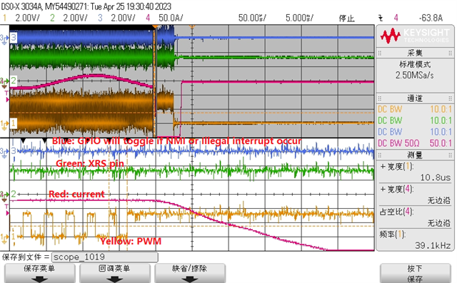
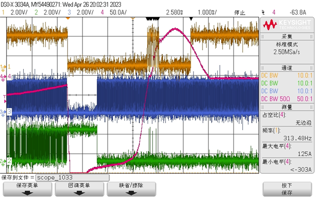
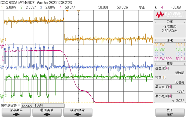
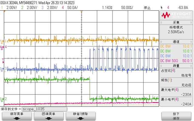
They capture the waveform as below, Red one is current waveform, yellow is EPWM2B from MCU which will have a very long high level pulse, then lead to over current.

blue is gpio toggle signal at PWM interrupt, also is abnormal to when issue occur. 

Customer have configure TZ1 for over current protection, they have verified TZ1 can signal well by suddenly add a very big load and TZ1 can be trigger to shun down PWM.

but in this case when there have some noise( connected to probe of scope will increase noise), TZ1 does not work to go to protection.

Emulator can not be connected to see the status of MCU as this is test in aging oven. 

but from waveform that seem MCU still working and may have missing clock without reset. 

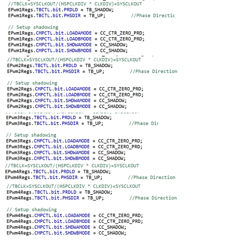
I suggest them to add TZ5 configure for clock fail, they use OSC2 for clock, configure as below:

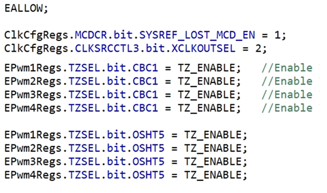
But seem does not work and TZ5 seem not happen to shut down PWM,  any missing to configure TZ5? any other suggestion to help fix this issue? thanks. 

  • Hi Strong ZHANG,

    Could you share the customer's shadow loading settings for their action qualifer events and CMP registers? This unexpected long pulse is usually due to shadow loading not being properly used. Refer to the "Waveforms for Common Configurations" section of the TRM to make sure the customer is meeting all of the requirements outlined in this section.

    If the customer is meeting all of those requirements, could you determine if they are using global load? There is another possible cause for this issue related to global loading, but I will need to consult with other EPWM experts to understand this case better.

    Thank you,

    Luke

  • Luke,

    Please refer to the configuration code, they did not use global load. 

  • Luke,

    Our focus work is not why there have long high level pulse, is that when there have long high level PWM pulse, why TZ protection did not work. 

    we do more test today, we add GPIO toggle and shut down pwm in NMI interrupt and illegal interrupt, once there have NMI interrupt and illegal interrupt, there will have a GPIO to toggle to indicate the code whether goto NIM or  illegal interrupt.

    we measure this GPIO signal and XRS, when over current occur, we can see what state of MCU is.

    we can see above waveform that there is no NMI/illegal interrupt happen and MCU reset happen when over current occur,

    they actually will shut down by soltware one shot TZ in NMI/illegal interrupt. 

    this time they did not have enough channel to monitor PWM interrupt, but they have do test many times that when over current occur, PWM interrupt will stop as there have one GPIO toggling to indicate whether PWM interrupt work(see previous waveform).

    There are two question that I can not explain:

    1. Why TZ protection did not occur? they have verify TZ1 work by suddenly adding a big load, over-current protection do work.

    also they verify TZ5 work when disconnecting external clock.(They use OSC2 usually, use external clock only for test).

    2. Why would PWM interrupt stop when over current occur but there is no NMI/illegal interrupt or reset? 


  • Hi Strong ZHANG,

    In order for the trip events to take effect, you must also configure the TZA and TZB bits in the TZCTL register. These bits configure what state the EPWM outputs will go into when a trip event occurs. By default the outputs are configured to go into a high impedance state which may be why you are observing abnormal behavior.

    Has the customer configured the TZA and TZB bits?

  • Hi Luke,

    customer do configure TZA adn TZB as below, at the beginning they use CBC trigger, I suggest them to use one shot, but seem the result is the same. 

    They have verified TZ signal can work by toggling TZ pin by manual when in normal working state. 

    They capture more waveform when fail:

    1. CH1(Yellow):OCP signal(TZ pin)

    CH2(Green):EPWM1B signal

    CH3(Blue):Toggle GPIO in PWM interrupt to indicate PWM interrupt is response 

    CH4(Red):Current waveform

     Above two waveform are when over current occur, 

    1. TZ pin signal was toggle when over current occur.

    2. PWM interrupt did not work.

    3. PWM output is always high which last for many PWM periods and about 1.3ms.

    Then MCU will reset, PWM interrupt resume to work as below showed.

    As MCU reset, it is unable to read the PWM registers as these will be clear by reset.

    Any suggestion for this issue?

  • Hi Strong,

    Is the customer modifying their TBPRD during runtime? I discussed this issue with another one of our EPWM experts, and he believes the most likely cause of this issue is an error calculating TBPRD or CMP values during the EPWM interrupt. The reason for this is that the EPWM interrupt stops occurring, which would mean the issue is not isolated to the TZ not working properly. Even if the trip was not functioning as expected, EPWM interrupts would continue to occur if this issue was isolated to the trip signal not driving the output to its expected state.

    Would it be possible to add a check in the EPWM interrupt that tests whether the calculated TBPRD or CMPA values are exceeding a specified value?