This thread has been locked.

If you have a related question, please click the "Ask a related question" button in the top right corner. The newly created question will be automatically linked to this question.

TMS320F280039C: question regarding the CAN remote / response frame transmission

Part Number: TMS320F280039C
Other Parts Discussed in Thread: C2000WARE

Hi folks.

I am trying out some application using the CAN remote / response mechanism. 

I first ran the example code from the C2000Ware, the can_exp7_loopback_tx_rx_remote_frame.c, and it operates as expected with no issue, showing that the received data is exactly the pre-set value in the IF1DATA & IF1DATB registers send buffer.

And then in my application, I have a local variable that is changing, and every a while an external device will send a remote frame to request it. I am expecting on the launchpad it should prepare the instant value of the variable in the register, so to be responded upon remote request. So I made some modification to the can_exp7_loopback_tx_rx_remote_frame.c like
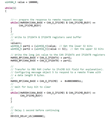
basically, the code is just same as the chunck in can_exp7_loopback_tx_rx_remote_frame.c, but moved into a while loop, since I hope to refresh the variable's value every a while (and get ready to new request). Also, I changed the message_obj_id to 5,  different with the example in can_exp7_loopback_tx_rx_remote_frame.c in which is 2. I assume the HWREG_BP(CANA_BASE + CAN_O_IF1CMD)  =  0x00830005UL;  in my code is doing the right thing.  

I tried with this script, and ensure that hardware connection is all fine. But I noticed that I can only receive the reponse from the other end for only once, (the value it got is correct. but after that, the new remote requests got no response.) which is not what I expect. 

What did I miss here? Thanks for your advice.

Regards,

Wei

  • Wei, 

    I tried recreating the conditions (using the loop you have attached) that you mentioned and was able to get a response to the remote request multiple times. 

    This implies that there must be something else wrong with your setup. 

    Without updating the data multiple times, can you try to check if there is response to multiple remote requests from an external device (this is to make sure that external device setup is working properly)

    Please share the results for the same and then we can debug further accordingly.

    Thanks.

  • Thanks Sahil for testing that.

    I realized that my description is not that accurate. The complete c script I am using is not in the similar structure like can_exp7_loopback_tx_rx_remote_frame.c.

    The whole script I am using adopts the interrupt for handling the CAN remote / response messages, lilke what is done in can_exp2_loopback_interrupts example.  Let me put the whole scritp here to simplify the reproduction.

    Thanks in advance for your time.

    Regards,

    Wei

    //
    // Included Files
    //
    #include <string.h>


    #include "driverlib.h"
    #include "device.h"


    //
    // Defines
    //
    #define MSG_DATA_LENGTH 8

    #define MSG_OBJ_ID_GET_RES 3
    #define MSG_ID_GET_RES 0x157

    #define MSG_OBJ_ID_GET_RES_RESPONSE 5
    #define MSG_ID_GET_RES_RESPONSE 0x158
    //
    // Globals
    //

    volatile uint32_t txMsgCount = 0;
    uint32_t txMsgSuccessful = 1;

    union TxMsgBuf {
    unsigned char txMsgData[8];
    uint64_t txWhole;
    }txMsgBuf;

    volatile uint32_t rxMsgCount = 1;

    uint16_t rxData[4];
    union RxMsgBuf {
    unsigned char rxMsgData[8];
    uint64_t rxWhole;
    }rxMsgBuf;

    volatile unsigned long i;
    volatile uint32_t errorFlag = 0;

    //
    // Function Prototypes
    //
    __interrupt void canaISR(void);

    //
    // Main
    //
    void main(void)
    {
    //
    // Initialize device clock and peripherals
    //
    Device_init();

    //
    // Initialize GPIO and configure GPIO pins for CANTX/CANRX
    // on module A.
    //
    Device_initGPIO();
    GPIO_setPinConfig(DEVICE_GPIO_CFG_CANRXA);
    GPIO_setPinConfig(DEVICE_GPIO_CFG_CANTXA);

    //
    // Initialize the CAN controllers
    //
    CAN_initModule(CANA_BASE);

    //
    // Set up the CAN bus bit rate to 500kHz for each module
    // Refer to the Driver Library User Guide for information on how to set
    // tighter timing control. Additionally, consult the device data sheet
    // for more information about the CAN module clocking.
    //
    CAN_setBitRate(CANA_BASE, DEVICE_SYSCLK_FREQ, 500000, 20);

    //
    // Enable interrupts on the CAN A peripheral.
    //
    CAN_enableInterrupt(CANA_BASE, CAN_INT_IE0 | CAN_INT_ERROR |
    CAN_INT_STATUS);

    //
    // Initialize PIE and clear PIE registers. Disables CPU interrupts.
    //
    Interrupt_initModule();

    //
    // Initialize the PIE vector table with pointers to the shell Interrupt
    // Service Routines (ISR).
    //
    Interrupt_initVectorTable();

    //
    // Enable Global Interrupt (INTM) and realtime interrupt (DBGM)
    //
    EINT;
    ERTM;

    //
    // Interrupts that are used in this example are re-mapped to
    // ISR functions found within this file.
    // This registers the interrupt handler in PIE vector table.
    //
    Interrupt_register(INT_CANA0,&canaISR);

    //
    // Enable the CAN-A interrupt signal
    //
    Interrupt_enable(INT_CANA0);

    CAN_enableGlobalInterrupt(CANA_BASE, CAN_GLOBAL_INT_CANINT0);

    // //
    // // Initialize the receive data message object used for receiving remote CAN messages.
    // // Message Object Parameters:
    // // CAN Module: A
    // // Message Object ID Number: MSG_OBJ_ID_GET_RES
    // // Message Identifier: MSG_ID_GET_RES
    // // Message Frame: Standard
    // // Message Type: Receive
    // // Message ID Mask: 0x0
    // // Message Object Flags: Receive Interrupt
    // // Message Data Length: (Note that DLC field is a "don't care"
    // // for a Receive mailbox
    // //
    CAN_setupMessageObject(CANA_BASE, MSG_OBJ_ID_GET_RES, MSG_ID_GET_RES,
    CAN_MSG_FRAME_STD, CAN_MSG_OBJ_TYPE_RX, 0,
    CAN_MSG_OBJ_RX_INT_ENABLE, 8);
    //
    //
    // //
    // // Initialize the receive data message object used for response CAN remote messages.
    // // Message Object Parameters:
    // // CAN Module: A
    // // Message Object ID Number: 5
    // // Message Identifier: MSG_ID_GET_RES_RESPONSE
    // // Message Frame: Standard
    // // Message Type: Receive
    // // Message ID Mask: 0x0
    // // Message Object Flags: 0
    // // Message Data Length: 0
    // // for a Receive mailbox
    // //
    CAN_setupMessageObject(CANA_BASE, MSG_OBJ_ID_GET_RES_RESPONSE, MSG_ID_GET_RES_RESPONSE,
    CAN_MSG_FRAME_STD, CAN_MSG_OBJ_TYPE_RXTX_REMOTE, 0,
    0, 8);


    txMsgBuf.txWhole = 0UL;
    rxMsgBuf.rxWhole = 0UL;

    //
    // Start CAN module A operations
    //
    CAN_startModule(CANA_BASE);


    uint64_t value = 100000;

    while(1)
    {


    //--- prepare the response to remote request message
    while((HWREGH(CANA_BASE + CAN_O_IF1CMD) & CAN_IF1CMD_BUSY) ==
    CAN_IF1CMD_BUSY)
    {
    }
    //
    // Write to IF1DATA & IF1DATB registers send buffer
    //
    value++;
    uint32_t part1 = (uint32_t)value; // Get the lower 32 bits
    uint32_t part2 = (uint32_t)(value >> 32); // Get the upper 32 bits

    // Write the long int value to the CAN IF1DATA and IF1DATB registers
    HWREG_BP(CANA_BASE + CAN_O_IF1DATA) = part1;
    HWREG_BP(CANA_BASE + CAN_O_IF1DATB) = part2;

    //
    // Transfer to MBX RAM (refer to IFxCMD bit field for explanation).
    // Configuring message object 5 to respond to a remote frame with
    // a data length 8 bytes.
    //
    HWREG_BP(CANA_BASE + CAN_O_IF1CMD) = 0x00830005UL;
    //
    // Wait for busy bit to clear
    //
    while((HWREGH(CANA_BASE + CAN_O_IF1CMD) & CAN_IF1CMD_BUSY) ==
    CAN_IF1CMD_BUSY)
    {
    }

    //
    // Delay 1 second before continuing
    //
    DEVICE_DELAY_US(1000000);


    }

    //
    // Stop application after completion.
    //
    asm(" ESTOP0");
    }

    //
    // CAN A ISR - The interrupt service routine called when a CAN interrupt is
    // triggered on CAN module A.
    //
    __interrupt void
    canaISR(void)
    {
    uint32_t intr_status;
    uint32_t can_status;

    //
    // Read the CAN-B interrupt status to find the cause of the interrupt
    //
    intr_status = CAN_getInterruptCause(CANA_BASE);

    //
    // If the cause is a controller status interrupt, then get the status
    //
    if(intr_status == CAN_INT_INT0ID_STATUS)
    {
    //
    // Read the controller status. This will return a field of status
    // error bits that can indicate various errors. Error processing
    // is not done in this example for simplicity. Refer to the
    // API documentation for details about the error status bits.
    // The act of reading this status will clear the interrupt.
    //
    can_status = CAN_getStatus(CANA_BASE);

    // //
    // // Check to see if an error occurred.
    // //
    // if(((status & ~(CAN_STATUS_TXOK)) != CAN_STATUS_LEC_MSK) &&
    // ((status & ~(CAN_STATUS_TXOK)) != CAN_STATUS_LEC_NONE))
    // {
    // //
    // // Set a flag to indicate some errors may have occurred.
    // //
    // errorFlag = 1;
    // }
    // else if(((status & ~(CAN_STATUS_RXOK)) != CAN_STATUS_LEC_MSK) &&
    // ((status & ~(CAN_STATUS_RXOK)) != CAN_STATUS_LEC_NONE))
    // {
    // //
    // // Set a flag to indicate some errors may have occurred.
    // //
    // errorFlag = 1;
    // }
    }


    else if(intr_status == MSG_OBJ_ID_GET_RES)
    {
    //
    // Get the received data
    //
    CAN_readMessage(CANA_BASE, MSG_OBJ_ID_GET_RES, rxData);

    //
    // Getting to this point means that the RX interrupt occurred on
    // message object 1, and the message RX is complete. Clear the
    // message object interrupt.
    //
    CAN_clearInterruptStatus(CANA_BASE, MSG_OBJ_ID_GET_RES);
    //
    // Since the message was received, clear any error flags.
    //
    errorFlag = 0;
    }

    //
    // If something unexpected caused the interrupt, this would handle it.
    //
    else
    {
    //
    // Spurious interrupt handling can go here.
    //
    }

    //
    // Clear the global interrupt flag for the CAN interrupt line
    //
    CAN_clearGlobalInterruptStatus(CANA_BASE, CAN_GLOBAL_INT_CANINT0);

    //
    // Acknowledge this interrupt located in group 9
    //
    Interrupt_clearACKGroup(INTERRUPT_ACK_GROUP9);
    }

  • Wei, 

    I am looking into it and will get back to you soon.

    Thanks.

  • Wei, 

    Apologies for the late reply. 

    I went thru your entire code and do not see anything out of order. Have you conducted tests to check whether the transmitter is sending frames properly? Check if multiple frames are being received in a loop first. Please let us know the results for that, after which we can look into further details.

    Thanks.

  • Hi Sahil,

    Not sure where I missed, but the code now works fine. Thanks for the reply.
