Other Parts Discussed in Thread: CONTROLSUITE
Hi team,
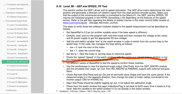
Customer connects encoder as required while debugging TMDSHVMTRPFCKIT level 3B. According to the doc, turn on the interrupt, LSW=1, and slowly increase the bus voltage, the motor starts to spin. However, the scope does not display the encoder angle, as shown in figure 1 below:
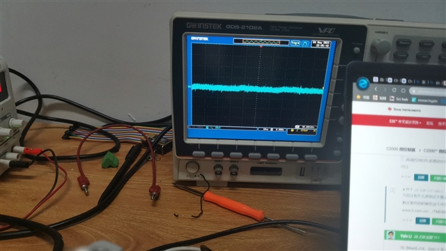
Figure 1
According to leven3B, the speed value in the speed1 structure should be equal to a given speed, but the value in this section is always 0, as shown in the following figure 2:
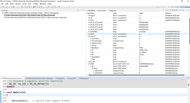
Figure 2
The encoder angle is reviewed in the program with the following statement: Pwmdac1.MfuncC2 = speed1.ElecTheta, as shown in the following figure 3:
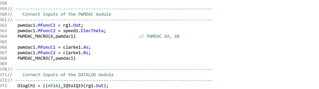
Figure 3
(The programs are located in controlSUITE\development_kits\HVMotorCtrl+PfcKit_v2.1\HVPM_Enhanced_Sensorless_2803x)
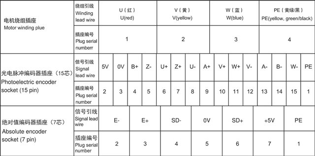
Using a 15-wire encoder (a+ B+ Z+ a- B- Z- U+ V+ W+ U- V- W- shielded wire), connect a+ B+ Z+ 5V GND to the five headers a/B/I/5V/0 respectively in the coding section of the TMDSHVMTRPFCKIT device.
In the CCS Debug interface, the QPOSCNT in the eQEP register remains the same with only QUTMR tripping, as shown in the following figure 4:
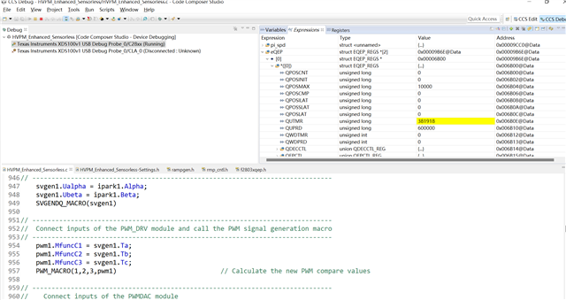
Could you help check this case? Thanks.
Best Regards,
Cherry