This thread has been locked.

If you have a related question, please click the "Ask a related question" button in the top right corner. The newly created question will be automatically linked to this question.

LAUNCHXL-F28379D: Unexpected interrupt overflow of ADC

Part Number: LAUNCHXL-F28379D

Hi Team, seeking some support for a customer

Facing a problem due to the appearance of interrupt overflows of ADC. 

/cfs-file/__key/communityserver-discussions-components-files/171/sn_5F00_customerservice_5F00_case_5F00_2eb04fc01bbe2190aecaf436464bcbb0_5F00_attachments.zip

I have 11 measurements to acquire : i put 6 measure on ADCA, 1 on ADCB, and 4 on ADCC.


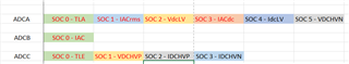
I use only one interrupt, linked to EOC5 on ADCA as it shall be the last one to be acquired.

Every SOC is triggered by EPWM1, with a frequency of 200kHz.

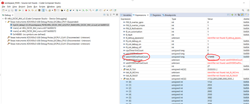
On the interrupt of ADCA1, I store the value in a table of 32 values.

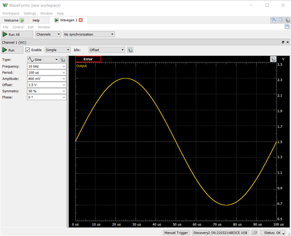
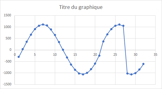
In input on the board, I have a perfect sinus voltage. However, in my table, I usually get parts of it :


The value in my table can be (for example) :


I checked the interrupt overflow counter and it increases all the time.


To investigate a bit more, each time the ADCA1 interrupt is called, i toggle a gpio output : I should see a perfect sware wave signal at a frequency of 100Khz but that it is not the case :


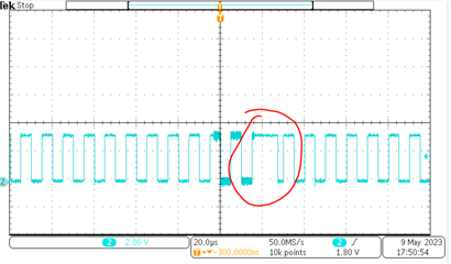
It confirms there are overflows.

As the ADC is capable of 3.3MSps in 12 bits, a frequency of 200kHz should not be a problem, even with 6 channels used on ADCA.


Do you have an idea what is wrong in my understanding ?

____________________-

Thank you very much in advance.

-Mark

  • Hello Mark,

    I will try to look into this by the end of the day, I need to confirm something with another expert.

    Best regards,

    Omer Amir

  • Hi Mark,

    Can you make sure there are no extra instructions that would cause the overall ISR execution to be greater than sampling and conversion of the ADC? You should be able to measure cycle duration when running the project in debug mode, you may have to check all conditional paths you may have.

    Best regards,

    Omer Amir

  • HI Omer, Here is the response of my customer.

    Used both methods described in (software-dl.ti.com/.../ccs_counting_cycles.html) to know the number of SYSCLK ticks that the function adcA1ISR requires : I

    found 149 by the first method and 162 by the second one, meaning a time of 800ns (SYSCLK = 200MHz).

    This number can not explain that I get an overflow as the interrupt is triggered by EPWM1 set at a period of 5us. I noticed also something very important: the number of overflows is exactly the same that the number of time the function triggered by EPWM2 (period 1ms) occurs (see second attachment). The ADCA1 interrupt has a lower interrupt priority than EPWM2. 

    Hoping for your extended assistance.

    Thank you.

    -Mark

  • Hello Mark,

    As the interrupt overflow bit indicates that the previous interrupt flag has not been cleared, this means that when the ADC interrupt overflow occurs then the interrupt is taking too long in comparison to the sampling/conversion time of the ADC. You need to verify that all paths in the interrupt can be done with a latency that is less than this ADC sampling time (this is why the value read at point 28 in your sampled sine wave is such a large jump, because the interrupt took that much longer and the input sine wave changed by that amount).

    (see second attachment)

    Which attachment is this? Is it in the .zip file attached or one of the images?

    Best regards,

    Omer Amir

  • Hi Omar, the image

  • Hello Mark,

    This is the only way the overflow can occur (an interrupt is triggered when the interrupt flag is already set). No other conversions/triggers matter, only whatever trigger is causing the SOC. Essentially, this is what needs to be checked:

    1. What SOC is triggering the interrupt where adcA1ISROveFlowCount is being incremented?
    2. What is triggering this SOC to start its conversion?
    3. How frequently is this trigger occurring?
    4. How fast is the ISR able to execute at its slowest path through any conditionals within it? (I'm assuming this is 162 cycles based on the previous post, but just make sure that there isn't a possibility of some other longer conditional being reached)

    If the answer to #3 is less than or even close to the answer to #4, there is a possibility of overflow. However, the customer's response is not clear on what is actually triggering the SOC which triggers the interrupt, so I just want to double-check this. If the answer to #3 is consistently greater than the answer to #4, then let me know because this is probably some other sort of issue.

    Best regards,

    Omer Amir

  • Hi Omer, 

    1 - interrupt is triggered by SOC 5 (INT1) :
    ADC_setInterruptSource(ADCA_BASE, ADC_INT_NUMBER1, ADC_SOC_NUMBER5);
    ADC_enableInterrupt(ADCA_BASE, ADC_INT_NUMBER1);
    ADC_clearInterruptStatus(ADCA_BASE, ADC_INT_NUMBER1);
    2 - EPWM1A trigs the SOC :
    ADC_setupSOC(ADCA_BASE, ADC_SOC_NUMBER5, ADC_TRIGGER_EPWM1_SOCA,
    ADC_CH_ADCIN3, 15);
    baseTrig = EPWM1_BASE;
    EPWM_disableADCTrigger(baseTrig, EPWM_SOC_A);
    EPWM_setADCTriggerSource(baseTrig, EPWM_SOC_A, EPWM_SOC_TBCTR_U_CMPA);
    EPWM_setADCTriggerEventPrescale(baseTrig, EPWM_SOC_A, 1);
    EPWM_enableADCTrigger(baseTrig, EPWM_SOC_A);

    3 - EPWM1 period is 5us :
    period = 500-1; // 500*10ns = 5us
    EPWM_setTimeBasePeriod(baseTrig, period);
    EPWM_disableADCTrigger(baseTrig, EPWM_SOC_A);
    EPWM_setADCTriggerSource(baseTrig, EPWM_SOC_A, EPWM_SOC_TBCTR_U_CMPA);
    EPWM_setADCTriggerEventPrescale(baseTrig, EPWM_SOC_A, 1);
    EPWM_enableADCTrigger(baseTrig, EPWM_SOC_A);

    4 - yes, I measured 162 cycles, i.e 0.81 used

    5 - answer to #3 is consistently greater than the answer to #4, there is an issue.

  • Hello Mark,

    As a final check, have the customer toggle a GPIO pin within the ISR (once at the very beginning, and once at the very end), and also enable the SOCA trigger to be viewed on an external pin. The ePWM SOCA event trigger can be viewed by using the below function:

    SysCtl_enableExtADCSOCSource(SYSCTL_ADCSOC_SRC_PWM1SOCA);
    GPIO_setPinConfig(GPIO_8_ADCSOCAO);

    Also, even though your ePWM period is 5 us, what value is the CMPA triggered by?

    Best regards,

    Omer Amir

  • Hi Omer, this is the response of my customer.

    Figure 1 : yellow_is_ADCoverflow_while_blue_is_ADC_interrupt_function.png
    Yellow signal is a the detection of an overflow of ADCA (I toggle a pin in the overflow monitoring)
    Blue signal is the ADCA interruption function : at the very beginning, I write a 1 in the GPIO while at the end, I write a 0.

    The reason why a overflow is quite obvious : the ADC interrupt flag is raised but something prevents the interrupted function to be executed. So, at next time the flag raises, the function is called but the overflow is detected.

    Figure 2 : yellow_is_ADCoverflow_while_blue_is_SOCA.png
    Yellow signal is still a the detection of an overflow of ADCA (I toggle a pin in the overflow monitoring)
    Blue signal is the SOCA signal. I use the code you sent to get it on GPIO8.
    The SOCA is triggred on 1/4 of the period. I Tried 1/2*period and also when cnt=0. This parameter has no impact on the problem. Nothing special here.
    The next figure is the most disturbing for me.

    Figure 3 : yellow_is_ADCoverflow_while_blue_is_EPWM2_interrupt_function.png

    Yellow signal is a the detection of an overflow of ADCA (I toggle a pin in the overflow monitoring)
    Blue signal is the EPWM2 interruption function : at the very beginning, I write a 1 in the GPIO while at the end, I write a 0.

    It can be concluded that when the interrupted function EPWM2 is running, it prevents the ADC interrupt function to run.
    That is not what I expected as INT_ADCA1 has a CorePriority : 5 - 1
    and INT_EPWM2 has a CorePriority : 7 - 2.
    Normally, the lowerest priority takes over.

    Thank you.

    -Mark

  • Hello Mark,

    There are a few questions/conclusions I have for the customer based on the attached images and code:

    1. Looking at the attached code and yellow_is_ADCoverflow_while_blue_is_ADC_interrupt_function.png, I don't see where the GPIO is toggled at the end of the ISR function.
    2. For yellow_is_ADCoverflow_while_blue_is_SOCA.png and yellow_is_ADCoverflow_while_blue_is_ADC_interrupt_function.png, if your GPIO is configured correctly and I don't have it in the version of the code you sent me then it looks like the ADC interrupt is indeed shorter than the trigger frequency of the ePWM SOCA, so this more than likely is not the source of the problem.
    3. The yellow_is_ADCoverflow_while_blue_is_EPWM2_interrupt_function.png shows that the ePWM interrupt is happening before the ADC interrupt, and the ADC interrupt occurs during the time that the ePWM interrupt is occurring. Your conclusion about interrupts is incorrect; there is no nesting interrupts allowed, only one interrupt is handled at a time as determined by priority (priority does not determine which thread can interrupt within another ISR). You will need to fix this and then see if the overflow issue is still occurring.

    Based on point 3 above and your code, it looks like you have quite a few ISRs in use, make sure that none of these will delay the ADC interrupt otherwise you will continue to see the interrupt overflow.

    Best regards,

    Omer Amir

  • Hi Omer, here is our customer's feedback.

    __interrupt void epwm2ISR(void)
    {
    // Autorise l'interruption par une interruption plus prioritaire
    EINT;
    // DEBUG
    GPIO_writePin(GPIO_DEBUG3, 1);
    // My code here
    // ...
    // Clear INT flag for this timer
    EPWM_clearEventTriggerInterruptFlag(EPWM2_BASE);
    // Acknowledge interrupt group
    Interrupt_clearACKGroup(INTERRUPT_ACK_GROUP3);
    // DEBUG
    GPIO_writePin(GPIO_DEBUG3, 0);
    // Disable Interrupts
    DINT;
    }

    By doing that, the problem of ADC overflow disappeared.
    Could you tell if this is the solution to my problem ?

    Moreover, at the end, I will have 3 interrupted function : the 2 previously presented and an additionnal on SPIA.
    The order of priority requested is ADCA, then SPIA then EPWM2.

    What do I have to put in my SPIA and EPWM2 function to allow this behaviour ?

    _____________

    Thank you.

    -Mark

  • Hello,

    Could you tell if this is the solution to my problem ?

    If you're not interrupting another interrupt and nothing is else delaying the ADC ISR from being entered then yes, this is the solution (although your code snippet just looks like your disabling the interrupt after your ePWM ISR, so I'm not sure if that's what you intended).

    What do I have to put in my SPIA and EPWM2 function to allow this behaviour ?

    I will forward this question to another expert who can provide a more detailed answer.

    Best regards,

    Omer Amir

  • Moreover, at the end, I will have 3 interrupted function : the 2 previously presented and an additionnal on SPIA.
    The order of priority requested is ADCA, then SPIA then EPWM2.

    What do I have to put in my SPIA and EPWM2 function to allow this behaviour ?

    Can you tell me what sort of end-equipment the customer is designing for, and who the customer is?

  • You can close the case.

    François