This thread has been locked.

If you have a related question, please click the "Ask a related question" button in the top right corner. The newly created question will be automatically linked to this question.

LAUNCHXL-F28027F: TMS320F28027F

Part Number: LAUNCHXL-F28027F
Other Parts Discussed in Thread: MOTORWARE, DRV8323

Hello,
I am running a BLDC motor. The control is sensorless. If the motor is now driven to a stop so that it can not rotate further, the motor makes a knocking noise and jerks (torque increases and then drops again). This behavior is also seen under very heavy load (high torque). From my experience so far, when the motor is stopped (e.g. driving against an Anschlg) the current goes into limiting and the motor applies a constant torque. Do you have an explanation for this behavior / how do I get the motor to maintain a constant torque at the end stop?
With kind regards
Thomas

  • Which example lab/project are you using? Or your own algorithm?

    If the motor is now driven to a stop so that it can not rotate further, the motor makes a knocking noise and jerks (torque increases and then drops again)

    Do you have any measured current waveform to show this question?

    Do you have an explanation for this behavior / how do I get the motor to maintain a constant torque at the end stop?

    You want to maintain a constant torque at the end stop at any accuracy position without any vibration? 

  • Hello

    I use the FOC lab11a from motorware_1_01_00_18 as a base for my motor control.

    Thanks for supporting

  • Any more information to help us understand your questions? Measured current waveform? Detailed operation steps you did? What application you are working on?

  • Hi 

    it is a general question: "Is the behavior described before typical for sensorless FOC? Motor makes a knocking noise when driven against the end stop (can't turn any further)"

    best regards

    Thomas

  • "Is the behavior described before typical for sensorless FOC? Motor makes a knocking noise when driven against the end stop (can't turn any further)"

    It's related to the motor and the load. The motor with sensorless-FOC will be not very stable and have reverse rotation during the startup. Generally, the sensorless-FOC is better to run the motor at a higher speed, it's difficult to run the motor smoothly and stably at zero and very low speed. 

  • Hello
    I know that the FOC works from a minimum speed, but how to explain this knocking noise (I run the motor at rated speed and slow it down to zero, then I get this said noise. Is it because the field continues to rotate even though the rotor is already at standstill?

    With kind regards

    Thomas

  • Did you capture any current waveforms to show this question? And did you try to tune the acceleration and the gains of the speed PI regulator?

    Is there only noise during the deceleration process? Or any other process?

  • Hello Yanming
    Thank you for your patience.
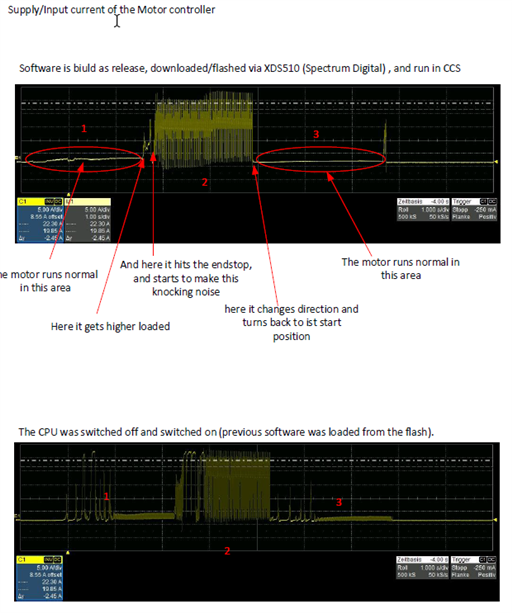
    My original question was about section 2 (see pdf file), where the motor hits the end stop and makes the knocking sound. Now, when adjusting the PID parameters of the speed controller, the following occurred; as long as I run the software in the CCS (release version is built and also flashed) the motor runs fine in the normal operating range (1,3). If I now unplug the XDS200 and turn the CPU off and on again, you can see a strong noise on the input current even extreme stomp peaks where the motor previously ran perfectly. The SW is the same as before. I would expect the motor to behave the same in both cases as I have seen in other projects. Do you have any idea what I have to change or do wrong?

    With kind regards
    Thomas Hecht

  • Any changes on the current hardware board you used?

    Can the motor works well if you always run the lab project within CCS by using the JATG emulator? Which example lab project are you using?

  • Hello Yanming,
    The board and the system are exactly the same (with and without the JTAG emulator connected), the difference is that the JTAG emulator has been removed and a power cycle has been performed (CPU has reloaded). If you start the software with CCS and JTAG emulator you have the good-natured behavior, then you can also remove the JTAG emulator, the behavior remains good-natured. As soon as you reset the CPU and boot it from the FLASH, you get the misbehavior. If you then connect the JTG emulator, nothing changes at first (system shows misbehavior), if you now connect the CPU (CCS: connect target) and load the symbols (CCS: load symbols...), you get the desired behavior (good-natured behavior / engine runs as intended). Is it possible that the CPU is running in a "debug mode"? Is it possible to detect this by the CPU registers?

    The Lab11a from the motorware_1_01_00_18 was used as basis.

    With kind regards
    Thomas Hecht

  • Seems like some of the variables are not initialized correctly in this standalone mode. What changes did you make compare to the example lab? Did you enable the CSM in your project?

  • Hello Yanming

    The define CSM_ENABLE is not set.

    The Lab11a is the base for my application, I added some things like timer interrupt, SCI interface (via interrupt) to switch the motor. I also adapted the usr.h file to our conditions like current/voltage scaling I initialize the DRV8323 with a scaling factor of Gain_10VpV, i.e. max. measurable current = 47.278A (reading back the DRV8323 also returns the value Gain_10VpV).
    -> USER_IQ_FULL_SCALE_CURRENT_A (40.0)
    USER_MOTOR_MAX_CURRENT (39.0) .

    If I understood this correctly CCS: "load Symbols" does not change anything at the program in the CPU, it only initializes the debugger? But how can it then lead to a different program behavior?
    Does CCS: "load Symbols" also initialize variables in the CPU?
    If yes - can you find somewhere a kind of list of variables to initialize (maybe compiler generated file or section in a file similar to the map-file)? Which variables (or memory area) does CCS initialize: "load Symbols"?

    with kind regards
    Thomas Hecht

  • If yes - can you find somewhere a kind of list of variables to initialize (maybe compiler generated file or section in a file similar to the map-file)? Which variables (or memory area) does CCS initialize: "load Symbols"?

    You may try to initialize the variables you used in your project, especially the value of the variables will be zero you assumed.

  • Thanks for your help, in the end it was because the DRV8323 was not yet enabled by the SPI bus during configuration. The enable signal is ANDed with an external signal, so the DRV8323 had its default parameters and the control loop became unstable.
    One more remark; in the file drv8323.c in the function DRV8323_readSpi the counter "WaitTimeOut" is defined as static and is not set to 0 when called again.
    (static volatile uint16_t WaitTimeOut = 0;). This leads to the fact that after cyclic call of the function the following while loop is left too early and the SPI read access is faulty (loop is left with timeout).

    with kind regards
    Thomas Hecht