Hi, As shown in the figure below, in one of my three-phase motor control applications I need to change one phase PWM from pulsing once to twice in a single PWM cycle while keeping the duty cycle (The advantage of this is that the harmonics of the motor stator current can be reduced at high modulation ratios).
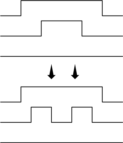
So, I define the PWM that needs to pulse twice as Mode4 and the PWM that only pulse once as Mode3, and use the function my_pwmB() to update the TBPRD, CMPA, CMPB and AQCTLA of the three-phase PWM for the next control cycle.
Here are the details of my_pwmB() function and the illustrative diagrams of the two emitting states, Mode3 and Mode4.
/*********************************   my PWM for DSP 28388 ***************************************/
// Explanations to array d for ePWM
// d=[TPRD,duty[6],Mode(3)]
// TPRD: PWM period in second (s)
// dABC: [dA,dA0,dB,dB0,dC,dC0], dA indicates EPwm1Regs.CMPB.bit.CMPB, dA0 indicates EPwm1Regs.CMPA.bit.CMPA (0~1)
// Mode: 3: pulse once, 4: pulse twice
/*********************************   my PWM for DSP 28388 ***************************************/
void my_pwmB(real32_T *d)
{
    uint16_T mode, i, *ePWM1Addr;
    uint16_T TPRD, dA, dA0;

    TPRD = (uint16_T) *(d+0);
    EPwm1Regs.TBPRD = TPRD;
    EPwm2Regs.TBPRD = TPRD;
    EPwm3Regs.TBPRD = TPRD;
    ePWM1Addr=(uint16_T *) (0x406B);  // Initial address for EPwm1Regs.CMPA.half.CMPA

    for (i=0;i<3;i++)  // correspond to Phase a, b, c
    {
        mode=(uint16_T) (*(d+7+i));
        dA=(uint16_T) (*(d+2*i+1) * TPRD);  // for CMPB
        dA0=(uint16_T) (*(d+2*i+2) * TPRD);  // for CMPA

        *(ePWM1Addr+i*0x100+2) =  dA;   // write EPwmiRegs.CMPB.bit.CMPB
        *(ePWM1Addr+i*0x100) = dA0;    // write EPwmiRegs.CMPA.bit.CMPA

        if (dA==TPRD) // 0%
                *(ePWM1Addr+i*0x100-0x2B)  = 0x1; //  CBD (00) CBU (00) CAD (00) CAU (00) PRD (00) ZERO clear (01)  [CBD CBU CAD CAU PRD ZRO]
        else if (dA==0) // 100%
                *(ePWM1Addr+i*0x100-0x2B)  = 0x2; //  CBD (00) CBU (00) CAD (00) CAU (00) PRD (00) ZERO set (10)  [CBD CBU CAD CAU PRD ZRO]
        else
        {
            if (mode==3) // mode=3,  (0--->1--->0)
                *(ePWM1Addr+i*0x100-0x2B)  = 0x601; //  CBD clear (01) CBU set (10) CAD (00) CAU (00) PRD (00) ZERO clear (01)  [CBD CBU CAD CAU PRD ZRO]
            else if  (dA==dA0) // mode=4 && CMPA==CMPB  (0%, When CMPB=CMPA, CMPA is invalid)
               *(ePWM1Addr+i*0x100-0x2B)  = 0x1; //  CBD (00) CBU (00) CAD (00) CAU (00) PRD (00) ZERO clear (01)  [CBD CBU CAD CAU PRD ZRO]
            else // mode=4 && CMPA!=CMPB  (0--->1--->0--->1--->0)
                *(ePWM1Addr+i*0x100-0x2B)  = 0x691; //  CBD clear (01) CBU set (10) CAD set (10) CAU clear (01)  ZERO clear (01)  [CBD CBU CAD CAU PRD ZRO]

        }
    }
}

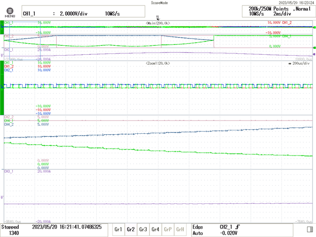
However, in the actual closed-loop motor operation, I found that there existed some individual cycles in the PWM that did not act as I had given them. In the screenshot of the oscilloscope, CH1_1, CH1_2, CH2_1 correspond to PWM1A, PWM2A, PWM3A respectively; CH2_2 represents the Mode of PWM1A, low level represents Mode3, high level represents Mode4; CH4_1 represents the value of EPwm1Regs.CMPB.bit.CMPB, 0V means CMPB is 0, 4.5V means the value of CMPB is equal to PRD (PRD=10000, PWM clock frequency is 100MHz), similarly, CH4_2 represents the value of EPwm1Regs.CMPA.bit.CMPA; CH3_1 indicates the motor stator current.
I put the DA output at the very beginning of the ADC interrupt, so there is no one-step delay between PWM and DA output in Oscilloscope screenshot.
You can see that the PWM waves 1 and 3 in the red frame belong to Mode4, but they do not pulse twice.

I also changed the timing of the sample trigger from CTR=ZRO to CTR=PRD, but the PWM in the red box of the oscilloscope screenshot below also belongs to Mode4, but only pulses once. Note that the DA output waveform in the screenshot will have a half-cycle delay compared to the PWM waveform because the ADC sampling time is modified here.

I'm trying to understand the reason why this is happening, would you mind giving me some advice for reference.
Sincerely,
Zhu