Part Number: TMDSCNCD28379D
Other Parts Discussed in Thread: SYSCONFIG, C2000WARE
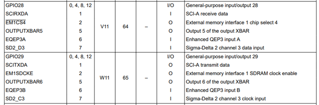
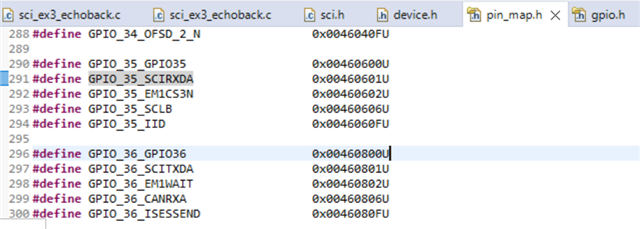
I am trying to get a serial communication sample (sci_ex3_echoback) to run on the subject board, but I need to use different pins for SCI-A Rx and Tx. The sample assigns SCIA Rx and Tx to pins 28 and 29 respectively. This appears to be done in file device.h, where several constants (_GPIO_PIN_SCI--- and _GPIO_CFG_SCI---) are defined. The processor documentation indicates pins 35 and 36 can also be used for Rx and Tx. I tried to revise device.h to use those pins, but when I run the program, it hits an error condition and stops.
The code that catches the error is:
rxStatus = SCI_getRxStatus(SCIA_BASE);
if((rxStatus & SCI_RXSTATUS_ERROR) != 0)
{
//
//If Execution stops here there is some error
//Analyze SCI_getRxStatus() API return value
//
ESTOP0;
}
I'll attach my revised file device.h so you can see how I attempted to re-assign the pins. Also, I searched the project files for occurrences of GPIO35. It appears in several .h files that all look like TI standard files.
Can you tell me what I need to do so that this program uses pins 35 and 36?