This thread has been locked.

If you have a related question, please click the "Ask a related question" button in the top right corner. The newly created question will be automatically linked to this question.

TMS320F28386D: tms320f28386d

Part Number: TMS320F28386D
Other Parts Discussed in Thread: SYSCONFIG, C2000WARE,

Hi Experts

I wanted  to use CLB block to control the motor commutation taking the 3 hall inputs and few more inputs to Generate 6 outputs.

For that I am thinking to use 3 LUTs and 3 OUTLUTs from each tile(2 tiles)

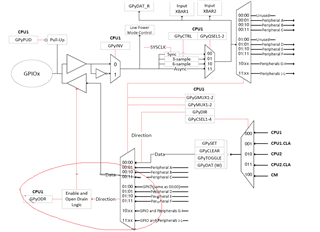
Please help me how to map GPIO inputs to the CLB and how to take outputs of the CLB to GPIOs

Thanks & Regards

K.Aravind

  • With reference to above query I would like to ask one more question i.e.,

    SYSCONFIG tool is showing BOUNDARY in (0 to 7), Does that mean we can only give 8 inputs.

  • Hi Aravind,

    Our C2000 Academy chapter on CLB has a good description on routing GPIOs into and out of the CLB module ( https://dev.ti.com/tirex/global?id=c2000Academy ). Essentially, you will want to use the CLB item in SysConfig (as opposed to the TILE item). You can then choose the number of inputs you want to bring into the CLB and where these inputs are coming from (either the global or local input bus or a GPREG). You are correct, each CLB tile can only have up to 8 inputs on a single configuration

    Regards,

    Peter

  • HI Peter,

    Thanks for the reply

    I have configured the CLB and made CLB_DEBUG and GENERATE_DIAGRAM = 1 in build->variable to generate html file but it is not generating for newly created project where as for example project it is generating.

    Please let me know what I am missing.

    Thanks,

    K. Aravind,

  • Hi Aravind,

    Looks like this thread accidentally got closed hence I am only just now seeing this response. How are you creating this new project? Are you making use of the empty CLB project within our C2000Ware or another empty project folder?

    Regards,

    Peter

  • Hi Peter,

    I am creating my own new project as follows.

    Selecting Project option from tool bar of CCS10 and selecting new ccs project.

    selected the device and created the project with empty main.c project

    Thanks & Regards,

    Aravind

  • Hi Aravind,

    I recommend you to use the "Import CCS project" option and import from the empty_projects example folder within our C2000WARE SDK. This should have the necessary post-build steps to generate the diagram and simulation files. Please let me know if you are able to do this

    Regards,

    Peter

  • Hello Peter,

    Thanks for the response

    I would like to know if there is any tutorials about configuring the clb tiles 

    Thanks,

    Aravind

  • Hi Aravind,

    Yes we have quite a few resources regarding the CLB. Please take a look at the CLB training module located at C2000 Academy: https://dev.ti.com/tirex/global?id=c2000Academy . At the bottom of the module, you will find links to other resources detailing the CLB and CLB configuration. Lastly, you can go through the CLB lab in C2000 Academy, which is step-by-step process of creating a project that makes use of the CLB module

    Regards,

    Peter

  • Hello peter,

    thanks for the response.

    I have gone through the example code from below path C:\ti\c2000\C2000Ware_4_03_00_00\driverlib\f2838x\examples\c28x\clb\CCS\clb_ex8_external_signal_AND_gate. I have understood the CLB as follows

    1. we have 8 CLB tiles for tms320f28386d

    2. Each CLB has 3 4input LUTs and 3 FSM and 3 counters and 8 OUTLUTs and we can connect them with each other within the CLB.

    3 And each CLB can have 8 inputs and 8 outputs.

    I have following doubts

    1. In the above mentioned example two signals are coming from external GPIOs, how that GPIOs is mapped to the CLB and where is that connection is established. How is that confirmed the GPIOs are connected to boundary in0 and boundary in1. I am missing the connection of external Pins to the CLB.

    2. It mentioned that we can take the CLB outputs from outputxbar, but outputxvbar is capable of driving only 8 outputs. in that case is it limited that using CLB we can only take 8 outputs  to the external pins or we can take more than 8 outputs to the external pins. if we can take more than 8 outputs how is that possible.

    Looking forward for your reply

    Thanks,

    Aravind.

  • Hi Aravind, 

    Your initial understanding of the CLB module structure is correct. To answer your questions:

    1. If you are using SysConfig, this GPIO to CLB allocation is done in the CLB menu located under the Control section

    This configures the BOUNDARY inputs for a specific CLB tile and then that tile is associated with the configuration created in the Configurable Logic Block option by calling the initTileX(CLBX_base) function.

    2. You are correct, you are limited by the number of CLB outputs on the CLB tile, up to 8. Do note that these signals are replicated so in addition to going to external pins, they can directly go to other peripherals on the device, look at the TRM for a detailed table of this.

    Regards,

    Peter

  • Hello peter,

    Yes I am using sysconfig tool 

    1.Can you please explain how gpio 0 and gpio 1 is mapped to the CLB boundary using the example I mentioned in my previous question.

    2. If I am using 2 tiles and can I take 16 outputs to the external gpio pins. If yes how is that possible.

    Please explain me with sysconfig configure example.

    Thanks, 

    Aravind.

  • Hi Aravind,

    1. GPIOs are input through the INPUT XBAR, after which they go into the CLBXBAR and assigned to the CLB Boundary input. This diagram below shows the general scheme from GPIO to CLB tile.

    2. Theoretically yes but you will be limited by the number of OUTPUTXBAR and CLB_OUTPUTXBAR on the device. See below as it is a similar path for both types of XBARs.

    Regards,

    Peter

  • Hello Peter,

    Its clear that outputs are taken from output_XBAR and CLB_outputXBAR

    my device is CLB type 3.

    1.So in type 3 can we take outputs from both output_XBAR  andCLB_outputXBAR ?  so that I can have upto 16 outputs onto the external gpio pins.

    Thanks,

    Aravind.

  • Hi Aravind,

    You are correct, type 3 CLB can take outputs from both output_XBAR and CLB_outputXBAR. Output_XBAR still maintains the restriction that it only has access to outputs 4 and 5 of each CLB tile, but CLB_outputXBAR can access any of the CLB tile outputs. There are 8 output_XBARs and 8 CLB_outputXBARs.

    So for two CLB tiles, you can output 4 outputs using output_XBAR (TILE1_out4, TILE1_out5, TILE2_out4, and TILE2_out5). You have 8 CLB_outputXBAR on the device, so you can output another 8 signals. This gives a total of 12 output signals to GPIOs for just two tiles. You then have 4 leftover output_XBAR so you can output another 4 signals from any of the remaining 6 remaining tiles (as long as these outputs are assigned to outputs 4 and 5 of their respective tile)

    To summarize, for x number of CLB tiles being used, the maximum number of output signals are as follows:

    1 CLB TILE -> 8 total output signals

    2 CLB TILEs -> 12 total output signals

    3 CLB TILEs -> 14 total output signals

    4 CLB TILEs -> 16 total output signals

    5 CLB TILEs -> 16 total output signals

    6 CLB TILEs -> 16 total output signals

    7 CLB TILEs -> 16 total output signals

    8 CLB TILEs -> 16 total output signals

    This assumes you aren't using the output_XBARs for any other peripherals

    Regards,

    Peter

  • Hello Peter,

    Thanks for the respose it was very helpfull.

    Now I am working on OUTPUTXBAR, can I control the GPIOs selected for the OUTPUTXBAR to be enabled or disabled. 

    Refering to the above diagram(page 1547 in reference manual) where I made a red circle.

    The inputs to mux is all pheripherals and GPIO, is OUTPUTXbar missing there.

    1) Is that a GPIO configured as OUTPUTxbar is defaultly selected as output and driven the default value just after power on ??

                   If yes, Can I disable or enable the GPIOs configured for OUTPUTXBAR whenever I wanted by using someother registers.

    Thanks,

    K. Aravind.

  • Hi Aravind,

    Please refer to the XBAR chapter for the diagram of how the OUTPUTXBAR is connected to the GPIO.

    In terms of enabling or disabling the GPIOs configured for the OUTPUTXBAR, you can make use of the OUTPUTxMUXENABLE registers to enable and disable the OUTPUTXBARs at any point in time. Typically, the GPIOs will output from the associated OUTPUTXBAR after you configure them in code, although since you are using the CLB, you can also choose to enable the OUTPUTXBAR output by calling the CLB_enableCLB function at the point in time when you want to activate the outputs. Although this will apply to all OUTPUTXBAR connected to the TILE

    Regards,

    Peter