Hi
The TMS320F28335: Example_2833xAdcSoc.c is working fine and it generates Digital values through 0-4095 when I apply a DC voltage(no freq) as input changing from 0 - 3V.. The ADC is converting this voltage as digital values accordingly on the watch window. The Graph window shows digital values settles (approx 0) at 0V DC input and at 3V DC input (approx 4095) respectively.
At 0V DC input ( The Graph window: Digital value -> approx 0)

At 3V DC input ( The Graph window: Digital value -> approx 4095)

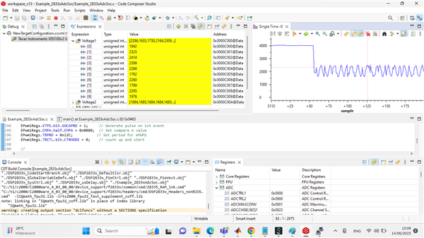
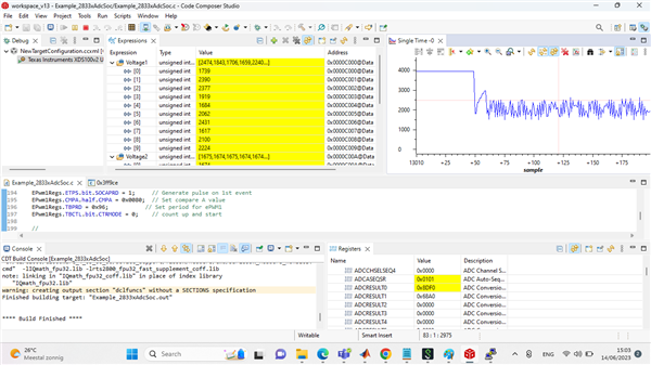
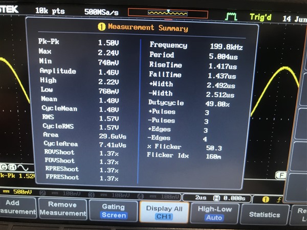
The Problem occurs when I apply a Sine wave of 3Vpeak-to peak at 200KHz or any other frequency less than 500Khz, The Graph window doesn't show the rise when the signal goes 3V. Secondly what changes do I need to do in the code for polarity if the voltage goes to -3V (negative) as input to see the digital value impact on the graph window. (See below picture)
Sine wave of 3Vpeak-to peak at 200KHz:

The code is attached here:
//###########################################################################
//
// FILE:   Example_2833xAdcSoc.c
//
// TITLE:  ADC Start of Conversion Example
//
//! \addtogroup f2833x_example_list
//! <h1> ADC Start of Conversion (adc_soc)</h1>
//!
//! This ADC example uses ePWM1 to generate a periodic ADC SOC on SEQ1.
//! Two channels are converted, ADCINA3 and ADCINA2.
//!
//! \b Watch \b Variables \n
//! - Voltage1[10]  - Last 10 ADCRESULT0 values
//! - Voltage2[10]  - Last 10 ADCRESULT1 values
//! - ConversionCount   - Current result number 0-9
//! - LoopCount     - Idle loop counter
//
//###########################################################################
// $TI Release: $
// $Release Date: $
// $Copyright:
// Copyright (C) 2009-2023 Texas Instruments Incorporated - http://www.ti.com/
//
// Redistribution and use in source and binary forms, with or without
// modification, are permitted provided that the following conditions
// are met:
//
//   Redistributions of source code must retain the above copyright
//   notice, this list of conditions and the following disclaimer.
//
//   Redistributions in binary form must reproduce the above copyright
//   notice, this list of conditions and the following disclaimer in the
//   documentation and/or other materials provided with the
//   distribution.
//
//   Neither the name of Texas Instruments Incorporated nor the names of
//   its contributors may be used to endorse or promote products derived
//   from this software without specific prior written permission.
//
// THIS SOFTWARE IS PROVIDED BY THE COPYRIGHT HOLDERS AND CONTRIBUTORS
// "AS IS" AND ANY EXPRESS OR IMPLIED WARRANTIES, INCLUDING, BUT NOT
// LIMITED TO, THE IMPLIED WARRANTIES OF MERCHANTABILITY AND FITNESS FOR
// A PARTICULAR PURPOSE ARE DISCLAIMED. IN NO EVENT SHALL THE COPYRIGHT
// OWNER OR CONTRIBUTORS BE LIABLE FOR ANY DIRECT, INDIRECT, INCIDENTAL,
// SPECIAL, EXEMPLARY, OR CONSEQUENTIAL DAMAGES (INCLUDING, BUT NOT
// LIMITED TO, PROCUREMENT OF SUBSTITUTE GOODS OR SERVICES; LOSS OF USE,
// DATA, OR PROFITS; OR BUSINESS INTERRUPTION) HOWEVER CAUSED AND ON ANY
// THEORY OF LIABILITY, WHETHER IN CONTRACT, STRICT LIABILITY, OR TORT
// (INCLUDING NEGLIGENCE OR OTHERWISE) ARISING IN ANY WAY OUT OF THE USE
// OF THIS SOFTWARE, EVEN IF ADVISED OF THE POSSIBILITY OF SUCH DAMAGE.
// $
//###########################################################################

//
// Included Files
//
#include "DSP28x_Project.h"     // Device Headerfile and Examples Include File

//
// Function Prototypes
//
__interrupt void adc_isr(void);

//
// Globals
//
Uint16 LoopCount;
Uint16 ConversionCount;
Uint16 Voltage1[10];
Uint16 Voltage2[10];

//
// Main
//
void main(void)
{
    //
    // Step 1. Initialize System Control:
    // PLL, WatchDog, enable Peripheral Clocks
    // This example function is found in the DSP2833x_SysCtrl.c file.
    //
    InitSysCtrl();

    EALLOW;
    #if (CPU_FRQ_150MHZ)     // Default - 150 MHz SYSCLKOUT
        //
        // HSPCLK = SYSCLKOUT/2*ADC_MODCLK2 = 150/(2*3)   = 25.0 MHz
        //
        #define ADC_MODCLK 0x3
    #endif
    #if (CPU_FRQ_100MHZ)
        //
        // HSPCLK = SYSCLKOUT/2*ADC_MODCLK2 = 100/(2*2)   = 25.0 MHz
        //
        #define ADC_MODCLK 0x2
    #endif
    EDIS;

    //
    // Define ADCCLK clock frequency ( less than or equal to 25 MHz )
    // Assuming InitSysCtrl() has set SYSCLKOUT to 150 MHz
    //
    EALLOW;
    SysCtrlRegs.HISPCP.all = ADC_MODCLK;
    EDIS;

    //
    // Step 2. Initialize GPIO:
    // This example function is found in the DSP2833x_Gpio.c file and
    // illustrates how to set the GPIO to it's default state.
    //
    // InitGpio();  // Skipped for this example

    //
    // Step 3. Clear all interrupts and initialize PIE vector table:
    // Disable CPU interrupts
    //
    DINT;

    //
    // Initialize the PIE control registers to their default state.
    // The default state is all PIE interrupts disabled and flags
    // are cleared.
    // This function is found in the DSP2833x_PieCtrl.c file.
    //
    InitPieCtrl();

    //
    // Disable CPU interrupts and clear all CPU interrupt flags:
    //
    IER = 0x0000;
    IFR = 0x0000;

    //
    // Initialize the PIE vector table with pointers to the shell Interrupt
    // Service Routines (ISR).
    // This will populate the entire table, even if the interrupt
    // is not used in this example.  This is useful for debug purposes.
    // The shell ISR routines are found in DSP2833x_DefaultIsr.c.
    // This function is found in DSP2833x_PieVect.c.
    //
    InitPieVectTable();

    //
    // Interrupts that are used in this example are re-mapped to
    // ISR functions found within this file.
    //
    EALLOW;  // This is needed to write to EALLOW protected register
    PieVectTable.ADCINT = &adc_isr;
    EDIS;    // This is needed to disable write to EALLOW protected registers

    //
    // Step 4. Initialize all the Device Peripherals:
    // This function is found in DSP2833x_InitPeripherals.c
    //
    // InitPeripherals(); // Not required for this example
    InitAdc();  // For this example, init the ADC

    //
    // Step 5. User specific code, enable interrupts:
    //

    //
    // Enable ADCINT in PIE
    //
    PieCtrlRegs.PIEIER1.bit.INTx6 = 1;
    IER |= M_INT1;      // Enable CPU Interrupt 1
    EINT;               // Enable Global interrupt INTM
    ERTM;               // Enable Global realtime interrupt DBGM

    LoopCount = 0;
    ConversionCount = 0;

    //
    // Configure ADC
    //
    AdcRegs.ADCMAXCONV.all = 0x0001;       // Setup 2 conv's on SEQ1
    AdcRegs.ADCCHSELSEQ1.bit.CONV00 = 0x3; // Setup ADCINA3 as 1st SEQ1 conv.
    AdcRegs.ADCCHSELSEQ1.bit.CONV01 = 0x2; // Setup ADCINA2 as 2nd SEQ1 conv.

    //
    // Enable SOCA from ePWM to start SEQ1
    //
    AdcRegs.ADCTRL2.bit.EPWM_SOCA_SEQ1 = 1;

    AdcRegs.ADCTRL2.bit.INT_ENA_SEQ1 = 1;  // Enable SEQ1 interrupt (every EOS)

    //
    // Assumes ePWM1 clock is already enabled in InitSysCtrl();
    //
    EPwm1Regs.ETSEL.bit.SOCAEN = 1;     // Enable SOC on A group
    EPwm1Regs.ETSEL.bit.SOCASEL = 4;    // Select SOC from from CPMA on upcount
    EPwm1Regs.ETPS.bit.SOCAPRD = 1;     // Generate pulse on 1st event
    EPwm1Regs.CMPA.half.CMPA = 0x0080;  // Set compare A value
    EPwm1Regs.TBPRD = 0xFFFF;           // Set period for ePWM1
    EPwm1Regs.TBCTL.bit.CTRMODE = 0;    // count up and start

    //
    // Wait for ADC interrupt
    //
    for(;;)
    {
        LoopCount++;
    }
}

//
// adc_isr -
//
__interrupt void
adc_isr(void)
{
    Voltage1[ConversionCount] = AdcRegs.ADCRESULT0 >>4;
    Voltage2[ConversionCount] = AdcRegs.ADCRESULT1 >>4;

    //
    // If 40 conversions have been logged, start over
    //
    if(ConversionCount == 9)
    {
        ConversionCount = 0;
    }
    else
    {
        ConversionCount++;
    }

    //
    // Reinitialize for next ADC sequence
    //
    AdcRegs.ADCTRL2.bit.RST_SEQ1 = 1;         // Reset SEQ1
    AdcRegs.ADCST.bit.INT_SEQ1_CLR = 1;       // Clear INT SEQ1 bit
    PieCtrlRegs.PIEACK.all = PIEACK_GROUP1;   // Acknowledge interrupt to PIE

    return;
}

//
// End of File
//
Please suggest
Thanks
Regards
Arsalan