


Part Number: LAUNCHXL-F28379D
Looking for some help with a 3 Phase PLL coded into LAUNCHXL-F28379D using Matlab/Simulink environment.
Used model similar to one shown below in Matlab/Simulink to program a LAUNCHXL-F28379D MCU.
The actual model I used had ADC's where sine wave blocks are shown and there was math function before the abc to dq block. The added math function subtracted the DC offset used in adc.
Also not shown is, a DAC, am using DAC_A (12-bit) on the LAUNCHXL-F28379D to monitor the theta signal. DAC_A is attached to output of "mod" block.
Anyway, code was successfully loaded onto MCU and ran successfully with exception.

At startup the theta waveform , monitored via DAC_A, looked good. (see below, magenta trace)

But then after a while the theta waveform starts to degrade, see below.
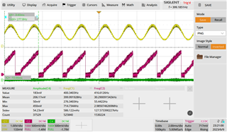
So my question is why is theta waveform degrading?
It seems that the resolution of the DAC is degrading.
Is it possible that the DC reference to the DAC is drifting over time?
Or is this a PLL issue?
Best,
Colin


