This thread has been locked.

If you have a related question, please click the "Ask a related question" button in the top right corner. The newly created question will be automatically linked to this question.

TMS320F280039C: turn up duty of PWM will cause disconnection with CCS

Part Number: TMS320F280039C
Other Parts Discussed in Thread: SFRA, UNIFLASH, C2000-GANG

Hi Team,

There's an issue from the customer need your help:

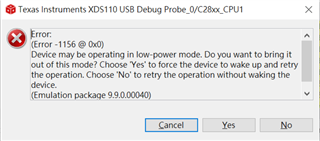
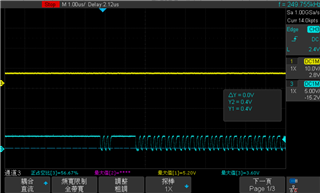
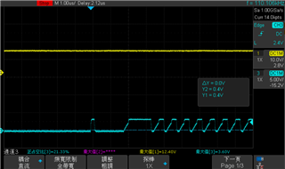
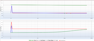
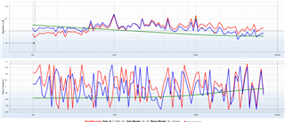
Hello, I am testing the BuckBoost routine. I use the 0039C development board to burn and then jump to the main circuit. There is no problem with the connection of CCS, but I use the XDS110 jumper to connect to the control board I designed. After the main circuit, I found that when I adjust the duty to be greater than 0.4, that is, the control board will be disconnected from the CCS when operating in equal voltage and Boost mode. I measured that the 3.3V of the control board is very stable. I would like to ask what is the problem. The picture below is the output voltage (yellow) and 3.3V (purple) on the control board when my duty is adjusted from 0.4 to 0.5

Could you help check this case?

Thanks & Regards,

Ben

  • here is the circuit  use for control board

    Among them, I did not use the MCU 1.2V, the oscillator is the internal oscillator of the MCU

  • Hi Ben,

    Are you able to monitor your JTAG signals (TMS, TCK, and TDI, TDO if you're using 4-pin JTAG) with an oscilloscope? It might be possible that noise from the buck boost module is causing connection problems.

    Best Regards,

    Ben Collier

  • Hi Benjamin,

    I use the 2-pin JTAG of TMS and TCK. I measured the TMS signal and found that it is an unstable signal.

    Later the following warning will be displayed

    Best Regards,

    Ben

  • Hi Ben,

    You will likely have to reroute the JTAG signals so that they are not near anything that might be switching for your buck boost.

    Best Regards,

    Ben Collier

  • Hi Benjamin,

    You will likely have to reroute the JTAG signals so that they are not near anything that might be switching for your buck boost.

    Does it mean that the PWM signal affects the programming signal? I am currently using a jumper to connect to the main circuit, away from the MOS, but it will still be disconnected.

    Best Regards,

    Ben

  • Hi Ben,

    Depending on the EPWM frequency and the board layout and schematic, yes the PWM could affect your JTAG signals. Are you isolating the buck-boost circuit from your C2000 device? Or are there common power and grounds? 

    Best Regards,

    Ben Collier

  • Hi Benjamin,

    The 5V voltage of my control board is provided by the main circuit, and the ground is also connected to the main circuit, but I have tried not to use the 5V of the main circuit but directly connect to the 3.3V of the development board, and it will still be disconnected from the CCS; another point, I tried to use the control board to connect to SFRA, and many times I tried to connect failed.

    Best Regards,

    Ben

  • Hi Ben,

    I would maybe recommend to try rerouting the JTAG traces on your board, but I am not exactly sure if your problem is being caused by EMI, or something like ground loops. It would be worth investigating what is causing the the voltage spikes that were observed on TMS. 

    I would definitely recommend that you review some TI EVMs like the following: 

    https://www.ti.com/tool/BOOSTXL-BUCKCONV

    https://www.ti.com/tool/TIDM-BUCKBOOST-BIDIR

    I would look for differences between these boards and your setup. 

    Best Regards,

    Ben Collier

  • Hi Benjamin, 

    To confirm, I use the TMS and TCK in the JTAG line of the XDS110 to jump directly to the TMS and TCK on the control board for programming, so the JTAG wiring mentioned above means the XDS110's wiring? If so, I probably won't be able to rewire it myself again, right?

    Thanks & Regards,

    Ben

  • Hi Ben,

    I was talking about rerouting the TMS and TCK traces on the control board. This may not solve the problem though, since this would only really help with EMI. 

    Please check out this article: https://software-dl.ti.com/ccs/esd/documents/xdsdebugprobes/emu_xds_target_connection_guide.html#buffered-case

    If your JTAG signals must travel farther than 6 inches, you may want to buffer your signals. There are also optional terminations that could help with signal quality. There are potentially other problems, though. I think it would be worthwhile to investigate what is causing the voltage spikes that you saw on the TMS pin.

    Like do you see these spikes only when your duty is above a certain level? Do the spikes get larger as duty increases? Can you run your device in standalone mode and see if there are still voltage spikes on the TMS and TCK pins at certain dutys? Also, why are there only spikes on TMS and not TCK?

    Best Regards,

    Ben Collier

  • these spikes only when your duty is above a certain level? Do the spikes get larger as duty increases?

    I had a spike when I didn't give Duty after burning, and the spike didn't get bigger when I increased the Duty

    Can you run your device in standalone mode and see if there are still voltage spikes on the TMS and TCK pins at certain dutys?

    I only burn into the control board. If I don’t connect the main board, there will be spikes, but it will not be disconnected from the CCS. When I only burn into the 0039C development board, there will be spikes.

    why are there only spikes on TMS and not TCK?

    The picture below is the signal of TCK

    When I measure the TMS signal, it is easy to make the following mistakes. This error does not exist when I do not measure. At this time, the TMS waveform is shown on the right.

    Best Regards,

    Ben

  • Ben,

    Could you look at the article that I linked in my last post? Since you are using jumper wires from a launchpad to your control board, the JTAG signals may be long enough to cause problems. Buffers may be necessary to help with your setup. Could you also try lowering the TCK frequency? 

    Best Regards,

    Ben Collier

  • Hi Benjamin,

    Could you look at the article that I linked in my last post?

    Yes, I have looked at other EVMs, it may be because of my control board wiring problem

    Could you also try lowering the TCK frequency? 

    I tried to lower it to 500k Hz and it still disconnected

    I want to try to burn the program into the flash of the control board for testing without connecting the CCS, but I have burned it many times, and the program will disappear after turning off the power every time. I have no problem burning it into the flash of the development board Yes, I would like to ask if the cmd file of the development board is different from my control board? Why can't I burn into the flash of the control board?

    In addition, I would like to ask if there is any other programmer that can be used for the MCU of 0039C besides connecting to XDS110 through CCS. For example, after giving the programmer an out file, one-click programming of single or multiple MCUs can be performed.

    Best Regards,

    Ben

  • Hi Ben,

    By default, F280039 will read GPIO24 and GPIO32 to determine the boot mode. Have you set these so that the control board will boot from flash? 

    The default Linker CMD file for flash should be fine for both the launchpad and your control board.

    There are several different JTAG Debug Probes that will allow you to program a single device including the XDS100, XDS200, and XDS560. These would allow you to program more than one device at a time, but you would need to configure your F280039 devices in a JTAG Daisy Chain, which is probably undesirable. 

    With these debug probes, you could use CCS or UNIFLASH to program your devices. Uniflash allows you to program your devices from the command line or batch files. 

    There is also this C2000-GANG programmer, which would allow you to program 8 identical devices at once: https://www.ti.com/tool/C2000-GANG

    I have not used the GANG programmer before, but it looks like it comes with its own GUI to help users get started.

    Best Regards,

    Ben Collier

  • Hi Benjamin,

    By default, F280039 will read GPIO24 and GPIO32 to determine the boot mode. Have you set these so that the control board will boot from flash? 

    I have no special settings for this part. I am currently using TI's routines. Is this part set in the CMD file?

    Regarding the problem of SFRA scanning, I am now connecting and burning the TMS and TCK on the control board through the XDS110 of the development board. I tried to use SFRA to scan and found that the wave line obtained is not correct. The left picture is no load, and the right picture is In the case of loading, can I use SFRA to scan if I only use the TMS and TCK pin connections?

    There is also this C2000-GANG programmer, which would allow you to program 8 identical devices at once:

    Are most of the programmers currently used in mass production C2000-GANG? Is there a way to provide C2000-GAND for us to test programming?

    Best Regards,

    Ben

  • Ben,

    I am not sure that I understand your question about using SFRA only when using TMS and TCK, could you please clarify? 

    It is my understanding that it is used for mid-sized production, while some larger customers have custom flash programming tools. I will have to investigate how to send a sample programmer. 

    Also, I sent you a friend request so that I could send you private messages, as we may not want to publicize the details of how to request samples. 

    Best Regards,

    Ben Collier

  • Hi Benjamin,

    I am not sure that I understand your question about using SFRA only when using TMS and TCK, could you please clarify? 

    At present, after I connect the USB cable to the development board, I only have to jumper the TMS and TCK two PINs on the development board to my control board, but the waveforms scanned by SFRA are severely jittered as shown in the figure below, and there is no way to use CompDesigner. For compensation, do I need to connect other PINs to use SFRA? Or is there another way to calculate the compensation parameter value?

    Best Regards,

    Ben

  • Ben,

    Are you also connecting the ground signals? I think that would be important. 

    Best Regards,

    Ben Collier

  • Hi Benjamin,

    Yes, and for more stable connect few more ground wires.

    Best Regards,

    Ben  

  • Ben,

    Just to confirm, your root problem is that you have connection issues with your control board when you adjust a duty cycle to be above 40%? 

    Do you only see the noisy scan when you are above that level, or do you see the same results when you are below this threshold? 

    Best Regards,

    Ben Collier