This thread has been locked.

If you have a related question, please click the "Ask a related question" button in the top right corner. The newly created question will be automatically linked to this question.

TMS320F280049C: CLA requires 4X more clock cycles to write to PWM registers than CPU

Part Number: TMS320F280049C


Hello,

I've noticed that PWM register writes in the CLA take significantly more time than the same writes by the CPU. For CLA writes I am seeing roughly 8-9 clock cycles per write and for the CPU I see about 2 clock cycles per write. 

I'm able to see this difference with the line below copied into either my CLA code or my CPU main ISR. However, I see the same difference if the "100.0" is a float variable, so I don't think it is a compiler optimization effect

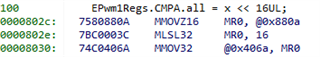
EPwm1Regs.CMPA.bit.CMPA = 100.0;

I am timing the instruction in the CPU by breakpointing on the instruction, resetting the Profile Clock in code composer and then stepping through the instruction. 

I am timing the instructions in the CLA using a PWM counter (PWM8) setup in the below code and then I subtract the counter value before/after the instruction 

timer_count1 = EPwm8Regs.TBCTR;

EPwm1Regs.CMPA.bit.CMPA = 100;

timer_count2 = EPwm8Regs.TBCTR-timer_count1;

I got the overhead of the timer access and subtraction by just doing the above timer code without anything in the middle as per below

timer_count1 = EPwm8Regs.TBCTR;

timer_count2 = EPwm8Regs.TBCTR-timer_count1;

The final clock counts were

CPU Instruction: 2
CLA Timer Overhead: 8

CLA Timer Minus Overhead: 16 - 8 = 8

Is this differential expected or does something seem to be off?

Thanks,
Jason


EALLOW;
EPwm8Regs.TBPRD = 32000; // Set period for ePWMx
EPwm8Regs.TBCTR = 0x0000; // Clear counter
EPwm8Regs.TBCTL.bit.CLKDIV = TB_DIV1; // Time-base Clock Prescale Bits
EPwm8Regs.TBCTL.bit.HSPCLKDIV = TB_DIV1; // High-Speed Time-base Clock Prescale Bits
EPwm8Regs.TBCTL.bit.SYNCOSEL = TB_SYNC_DISABLE; // EPWMx is a "slave", sync flow-through
//EPwm4Regs.TBCTL.bit.PHSEN = TB_ENABLE; // EPWMx is a "slave", Load the time-deg counter from TBPHS at sync
EPwm8Regs.TBCTL.bit.CTRMODE = TB_COUNT_UP; // Up-Down Count Mode
EDIS;

  • Realized I wrote 100.0 and float above, but in my test case I had 100 so there shouldn't be a float conversion in the assignments. 

  • here is the assembly code sections for the cpu and cla. Looks like PWM register reads give me the same assembly, but writes do not. CPU assembly is the top part

     345        EPwm1Regs.CMPA.bit.CMPA = 100;
    009838:   761F0101    MOVW         DP, #0x101
    00983a:   56BF642B    MOVB         @0x2b, #0x64, UNC
     347        test_read_cpu  = EPwm1Regs.CMPA.bit.CMPA;
    00983c:   922B        MOV          AL, @0x2b
    00983d:   761F02C3    MOVW         DP, #0x2c3
    00983f:   9611        MOV          @0x11, AL
    
    
        1101              ; 249 | EPwm1Regs.CMPA.bit.CMPA = 100;                                         
        1102              ;----------------------------------------------------------------------
        1103 000000bc 0000          MMOVIZ    MR1,#0                ; [CPU_FPU] |249| 
             000000bd 7841 
        1104 000000be 006B!         MMOVZ16   MR0,@_EPwm1Regs+107   ; [CPU_FPU] |249| 
             000000bf 7580 
        1105 000000c0 0004          MAND32    MR0,MR1,MR0           ; [CPU_FPU] |249| 
             000000c1 7C60 
        1106 000000c2 0064          MMOVXI    MR1,#100              ; [CPU_FPU] |249| 
             000000c3 7881 
        1107 000000c4 0004          MOR32     MR0,MR1,MR0           ; [CPU_FPU] |249| 
             000000c5 7C80 
        1108 000000c6 006B!         MMOV16    @_EPwm1Regs+107,MR0   ; [CPU_FPU] |249| 
             000000c7 75C0 
        1109 000000c8 0000          MNOP      ; [CPU_FPU] 
             000000c9 7FA0 
    
        1114              ; 251 | test_read  = EPwm1Regs.CMPA.bit.CMPA;                                  
        1117              ;----------------------------------------------------------------------
        1118 000000ce 006B!         MMOVZ16   MR0,@_EPwm1Regs+107   ; [CPU_FPU] |251| 
             000000cf 7580 
        1119 000000d0 0035-         MMOV16    @_test_read,MR0       ; [CPU_FPU] |251|          
    

  • Hi Jason,

    I apologize for the delay in response.

    The CLA does not have all of the instructions that the C28x does. 

    I suggest not using .bit if the register doesn't have fields that do not have to be preserved. The C28x can do a read-modify-write OR/AND/XOR instruction in one cycle. The CLA has to read, modify, write in separate instructions.

    For example:

    EPwm1Regs.DBFED.bit.DBFED = X  tells the compiler to write the value X to this register, but only modify the bits occupied by the bit-field DBFED.

    • To do this, the compiler must read the value
    • perform AND and OR operations to fill bits 0-13 with DBFED and still preserve bit 14 and 15
    • then write the value back.
    • For the CLA this takes 4 instructions. (read, AND, OR, write).

    By contrast EPwm1Regs.DBFED.all = X tells the compiler to write the value X to the register. This is fine since:

    • bits 15 and 14 are reserved and not used for anything.
    • They are read only
    • For the code shown below, this results in only a write instruction plus any setup to load the constant (MOVXI)

  • Hi Lori,

    Thanks for responding. Does this mean for CMPA/TBPHS etc updates since these registers are 32 bits, with the lower 16 being CMPAHR,TBPHSHR, we must use the bit field and deal with the 4 instructions or is there a workaround for this as well? 


    Thanks,
    Jason 

  • Jason,

    I have two possible options:

    If you aren't using the HR half, then you could shift the value by 16 - for example:

    Or you could modify the bit-field definitions themselves to split CMPA from CMPAHR. 

    Cheers,

    Lori