This thread has been locked.

If you have a related question, please click the "Ask a related question" button in the top right corner. The newly created question will be automatically linked to this question.

TMS320F280039C: How to write to OTP for standalone boot

Guru 12205 points
Part Number: TMS320F280039C
Other Parts Discussed in Thread: UNIFLASH, LAUNCHXL-F280039C

Hi, 

Write 0x5AFF1820 to Bootconfig (0xD00) and write 0xFFFF41FF to DefWordLow (0xD04) for emulation boot.
0x5AFF1820・・・- Lower 4 digits: GPIO24=0x18, GPIO32=0x20
0xFFFF41FF・・・ Since the SCI boot pins have been changed to GPIO8 and GPIO9, they are replaced with 0x41.

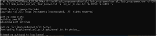
These values were written to RAM via CCS, and the SCI Flashkernel was successfully downloaded.

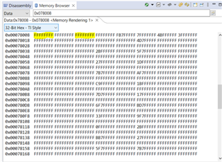
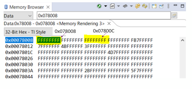
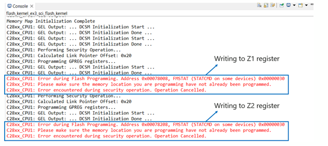
I plan to write to the OTP for standalone boot in the future, can you tell me what values I should write to addresses 0x00078008 (Z1 BOOTPIN Config) and 0x0007800C (Z1-GPREG3 BOOTDEF LOW0)?

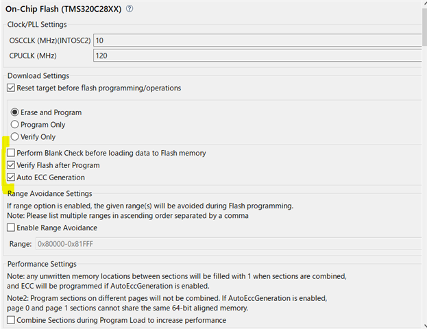
Also, please tell me the procedure to write to OTP with UniFlash or CCS.

Thanks,

Conor

  • Connor,

    You can re-use the same values you loaded in the EMU-xxx locations, just moving them to Z1-xxxx.

    In your .cmd file; you need to define the locations that correspond the the above BOOTPIN-CONFIG as well as BOOTDEF-LOW.  Under the "Page 1" area you will add

    Z1_OTP_BOOT_CONFIG : origin = 0x078008, length = 0x000002
    Z1_OTP_DEF_WORD_LOW : origin = 0x07800C, length = 0x000002

    In the main.c(or any .c in your project) file you now need to tell the compiler/linker what to place there(the same values that you wrote to EMU locations in RAM earlier), this will in the declaration section at the top of the file.

    #pragma DATA_SECTION(Z1_OTP_BOOT_CONFIG,"Z1_OTP_BOOT_CONFIG");
    #pragma DATA_SECTION(Z1_OTP_DEF_WORD_LOW,"Z1_OTP_DEF_WORD_LOW");


    const uint32 Z1_OTP_BOOT_CONFIG = 0x5AFF1820;
    const uint32 Z1_OTP_DEF_WORD_LOW = 0xFFFF41FF;  

    Best,
    Matthew

  • Hi Matthew,

    Page 1 is missing in the linker command file.
    I modified the program as you mentioned, but I still couldn't write to the OTP.

    Step 1.
    Add the following items to the memory area of the linker command file.
    Z1_OTP_BOOT_CONFIG : origin = 0x078008, length = 0x000002
    Z1_OTP_DEF_WORD_LOW : origin = 0x07800C, length = 0x000002

    Step 2.
    Add the following to the main code

    #pragma DATA_SECTION(Z1_OTP_BOOT_CONFIG,"Z1_OTP_BOOT_CONFIG");
    #pragma DATA_SECTION(Z1_OTP_DEF_WORD_LOW,"Z1_OTP_DEF_WORD_LOW");
    const uint32 Z1_OTP_BOOT_CONFIG = 0x5AFF1820;
    const uint32 Z1_OTP_DEF_WORD_LOW = 0xFFFF41FF;

    Please let me know if my steps are wrong. Just in case, I am sending you the CCS project.

    6320.flash_kernel_ex3_sci_flash_kernel.zip

    It would be very helpful if you could give me a project that changes the memory area of the above OPT just by writing.

    I also checked with UniFlash, but the following error occurred and I could not write.

    My purpose is to write values to Z1_OTP_BOOT_CONFIG and Z1_OTP_DEF_WORD_LOW, so it doesn't matter which tool you use, such as CCS or Uniflash.

    Thanks,

    Conor

  • Conor,

    please give me another day to try this out here on a 280039 device.

    matt

  • Conor,
    I'm not exactly sure why CCS is not programming the OTP, but there is another option to load these locations in the flash tool (in CCS) itself.

    In CCS if you select tools->On-Chip Flash it will open the flash tools window, if you scroll down there is a place to manually enter the 32-bit values we mentioned above.

    I don't see anything explicit in this tool that says "don't program OTP" when a .out is loaded, but the presence of the above option makes me curious if that is what is going on. 

    I know the underlying flash API that is used allows OTP programmation.

    Best,
    Matthew

  • Hi Matthew,

    I tried to write with the CCS you described, but I couldn't write with the following error. It seems that the OTP is locked.
    A similar phenomenon occurred with Uniflash.

    I don't mind using the API, so please guide me.

    Thanks,

    Conor

  • Conor,

    Can you open a memory window to those locations in OTP and copy the values/screenshot here?  0x78008-0x7800F

    Best,

    Matthew

  • Hi Matthew,

    Below is the memory map. What I want to know is how to write to OTP.

    Thanks,

    Conot

  • Conor,

    The memory map is showing both of the locations of interest as 0xFFFF or erased.  CCS should be able to program these to your values.

    Let me loop in some others for comment.

    Best,

    Matthew

  • Hi Matthew,

    I have written to the EVM and it writes successfully.

    Below is the memory map. What I want to know is how to write to OTP.

    The memory map is for EVM, so I will check tomorrow for the memory map for the custom board. (The custom board is currently not in hand, so we cannot check it.)

    Am I correct in understanding that if the OTP at address 0x078008 and address 0x07800C on the custom board is a value other than 0xFFFF, then the write has been done once?

    If it has already been written to the OTP, is there a way to write it again?

    ~Errors when writing OTP on custom boards~

    In parallel, we are also verifying the operation with EVM.

    The following values were written for the standalone firmware update
    Z1_OTP_BOOT_CONFIG = 0x5AFF1820
    Z1_OTP_DEF_WORD_LOW = 0xFFFF41FF

    I wrote these values and attempted to run serial_flash_programmer.exe.
    However, it stopped at the following screen.


    Can you give me some advice?

    In case of emulation boot, it works fine. The only way to determine if it is an emulation boot or a standalone boot is if it is connected to JTAG. These may be involved. Do I need to remove the jumper pins on the EVM, I'm not quite understanding the criteria for determining if JTAG is connected or not.

    Thanks,

    Conor

  • Conor,

    On the device in question, can you open another memory window to address 0x1071000 - 0x0107107F.  This contains the ECC syndromes for the DCSM OTP at addresses 0x78000-0x783FF, which we are trying to program.

    It is possible, that if the OTP was attempted to be written to 0xFFFF(even though that is erased) that the associated ECC syndrome was programmed and is not 0xFFFF.  If we see contents in the associated memory range then that would be why CCS is not allowing us to program, since the ECC is OTP as well.

    The serial loader maybe having the same issue with the EVM, so will wait for your reply on the above.

    In terms of emulation boot, I believe that the boot ROM is interrogating a register called "TAP_STATUS" that will indicate if the emulation logic is active or not.  This is more than JTAG being plugged in, but that the scan sequence to connect to the device is active/complete.

    Best,
    Matthew

  • Hi Matthew,

    The memory area of the custom board was the same.

    On the device in question, can you open another memory window to address 0x1071000 - 0x0107107F.  This contains the ECC syndromes for the DCSM OTP at addresses 0x78000-0x783FF, which we are trying to program.

    Referencing the area 0x1071000 - 0x0107107F, the following was found: 0x1071000 and 0x1071004 were values other than 0xFFFFFFFFFF.
    The DCSM OTP is most likely the problem. Can you give me some advice?

    Thanks,

    Conor

  • Hi Matthew,

    On the EVM side, memory address: 0x1071000 was 0xEBAAFFFFFF and other addresses were 0xFFFFFFFFFF.
    EVM was able to write to OTP successfully.

    EVM is connected to PC via USB via JTAG. Is it possible to run the SCI kernel stand-alone on EVM?

    Thanks,

    Conor

  • Conor,

    Since the boot modes are now programmed correctly, the SCI boot/kernel should now work.  Let me know if there are additional questions.

    Best,

    Matthew

  • Hi Matthew,

    I have not received an answer to what I want to know. I get an error on  custom board and cannot write to the OTP.
    Thus I am unable to try the standalone boot operation. Please comment on this. If you need any additional information, please let me know.

    Thanks,

    Conor

  • Hi Conor,

    The expert is out of office today, please expect a response back by tomorrow. Apologies for the inconvenience.

    --Luke

  • Thank you.

    I'll be waiting for repley from the expert.

  • Hi

    I would appreciate it if you could contact me with the results of the confirmation by the end of the day, as I would like to confirm it tomorrow.

  • Conor,

    I need some clarification on which device works and which device does not work to program the OTP.

    The EVM was able to program the OTP, when connected to CCS from the above message.

    On the EVM side, memory address: 0x1071000 was 0xEBAAFFFFFF and other addresses were 0xFFFFFFFFFF.
    EVM was able to write to OTP successfully.

    I was assuming that the previous board/device was not able to program the OTP successfully, which would prohibit us from programming it again.

    Let me know if I'm understanding this correctly.  I think the first point indicates that on a fresh device you can program things successfully, the other board/device will not be able to be re-used.

    Best,

    Matthew

  • Hi Matthew

    Organize the current situation. We have verified the operation with two Devices.
    The first is EVM (LAUNCHXL-F280039C).
    The second is F280039C on a custom board.
    The first EVM could be written successfully, but the second custom board has an error when writing OTP.

    The following is the error that occurred with F280039C on the custom board.

    The memory on the custom board is as follows.

    Writing to registers other than OTP can be done normally. Also, no writes have been made to OTP so far.

    Please respond as soon as possible as we are getting close to mass production. Please let me know if you need any additional information.

    Thanks,

    Conor

  • Conor,

    Do you have one more fresh custom EVM we can try to program the OTP?  The error message really seems to be pointing to a programmation event happening on the current EVM.  On a completely fresh device we shouldn't have any issues with the OTP for the first programmation.

    Best,

    Matthew

  • Hi Matthew,

    You may be mistaken. The custom board that is currently causing the error is not an EVM, but a prototype board.
    EVM was able to write successfully. We only have one prototype board on our hands, so we are unable to check for additional boards.
    We need to write OTP to the prototype board that we currently have. We need clarification on how to resolve the error.
    Is this error solvable? This error has been present since the first attempt to write to the OTP.

    Thanks,

    Conor

  • We will be debugging to resolve this error tomorrow. Your view by the end of the day would be greatly appreciated.

  • Conor,

    I think that this is related, based on the ECC I suspect that somehow the ECC OTP on the prototype board got written unintentionally.  Since this is OTP memory, once it is programmed there is nothing we can do to change it.

    Is there any additional units you have that we can replace the existing C2000 on the prototype with, or a 2nd proto board and try to program again?

    I think we may be able to use Z2 to supersede the  Z1 block GREG registers for this once device if this is the only one available.

    Best,

    Matthew

  • Hi Matthew,

    I do not have a 2nd proto board on hand.
    Can you please tell me the procedure to try the following?

    I think we may be able to use Z2 to supersede the  Z1 block GREG registers for this once device if this is the only one available.

    Thanks,

    Conor

  • Conor,

    In CCS, if you scroll down a bit in the flash tools window, you will see equivalent Z2GPREGs below the Z1GPREGs.  Before you program this, let's check to see that these are also 0xFFFF(erased).  This will take precendence over the Z1GPREG when written.  You can write the same values as you were before, just to these new locations.

    Matt

  • Hi Matt

    If a same error occurs when writing to the Z2GPREG, is it difficult to SCI boot (Stand-Alone) with this custom board?
    In other words, is the only way to replace the C2000 on the custom PCB with another chip?

    Thanks,

    Conor

  • Conor,

    That is correct, if we find that Z2 cannot be written then the only option is to replace the C2000 with a new one.  I will add that the only way that this could happen is if this region was programmed already.  If we see this fail, and have the same observation as Z1 that you didn't attempt a programmation we may have to understand if there was some automatic programming based on CCS settings, etc.

    Matt

  • Hi Matt,

    The following is the register before writing to the Z2 register.

    Afterwards, writing was performed to Z2 register, but the same error occurred as when writing to Z1 register.
    As we have not written to the OTP of the Z2 register in the past, we believe that there is a reason other than the OTP already being written to, why we cannot write to it.

    As we have sent you before, there is a high possibility that there are other causes, as several similar errors have occurred in E2E.
    Also, we are sorry to say that we are currently unable to replace the chip in the custom board with a new chip.

    Q1. Are there any settings that need to be made when using the CCS Onchip-Flash tool? For example, the yellow checkboxes below.

    Q2. Is it possible for me to try to write to the OTP using methods other than Uniflash and CCS's Onchip-Flash tool? For example, using the Flash API sample code. I would also like to know the procedure for doing so.

    Thanks,

    Conor

  • Conor,

    I believe you mentioned this before, but you can program the main flash array without issue on your custom PCB, correct? 

    This should eliminate any kind of board level issue, that would indicate the device voltage/clock isn't proper when we are trying to program the flash.  I just want to make sure we don't need to look at the schematic for something that is causing this.

    If you can program the main array successfully there shouldn't be any reason the OTP should be giving us issues.

    I don't believe the API programming is going to give any better results than the CCS tool at this point, we need to figure out why this issue is happening.

    For the replacing the device, is this an issue of inventory of our device, or more that the device cannot be easily replaced even if you had a spare.  I can try to help if this is an inventory issue.

    Best,

    Matthew

  • Hi Matthew,

    There has been progress.
    Two custom boards are now available. Assume that the custom board that has been operating until now is board A and the other one is board B.

    Board A - Cannot write to the OTP of both Z1 and Z2 blocks.

    Board B - Cannot write to the OTP of the Z1 block. However, it was possible to write to the OTP of the Z2 block; the error that occurred when trying to write to Z1 is the same as the error we sent you before. The memory of Z1 was 0xFFFFFF and there was no evidence of writing.

    Can you give us any comments based on these results?

    (We will be getting board C in the future and plan to verify writing to a chip that has never been written to.)

    Thanks,

    Conor

  • Connor,

    I'm going back a few messages when I had you look at the ECC memory that corresponds to the DCSM OTP.  For every 8 16-bit words(128 bits) of OTP there is a 16-bit ECC syndrome.

    Looking back at this picture, we see that 0x1071001(or the upper 16-bits of the 32-bit word at 0x1071000) has a non 0xFFFF value.  This indicates that at some point there was a call to the flash API to "program" all 0xFFFF to address 0x70008, and the ECC got written.

    If we extrapolate this to the Z2 GPREG1 OTP address 0x70208, then you can look at address 0x107141 to make sure it is 0xFFFF.  On both your devices you should see this as non-0xFFFF; on your first device this is what was keeping us from programming it, on your new device it will be non 0xFFFF intentionally as you have programmed the Z2 GPREG1 with the tool.

    When you get a fresh device, you can verify that the Z1 or Z2 programming should be successful by looking at 0x1071001 and/or 0x107141 and verifying they are 0xFFFF(in addition to the main addresses of 0x70008 and 0x70208).

    Best,

    Matthew

  • Hi Matthew,

    If we extrapolate this to the Z2 GPREG1 OTP address 0x70208, then you can look at address 0x107141 to make sure it is 0xFFFF.  On both your devices you should see this as non-0xFFFF; on your first device this is what was keeping us from programming it, on your new device it will be non 0xFFFF intentionally as you have programmed the Z2 GPREG1 with the tool.

    We first verified this with Board A. We could not access 0x107141. 

    Is there a mistake in the description of 0x1071041? If so, the following was the case.

    Verification of Boards B and C will be carried out in the future. If what you are saying is correct, then 0xFFFF has been written to the Z1/Z2 GPREG1 OTP by calling the Flash API. However we are puzzled as we do not recall writing it intentionally. So we need to investigate which procedure was at fault. Is it possible for the user to write unintentionally, e.g. during debugging?

    Thanks,

    Conor

  • Conor,

    Apologies for the typo on the 2nd ECC address.  You are correct with your 2nd window address.

    I think it would be unlikely that your code would accidentally write to this region, since it is address wise located prior to the main array.  There is a button at the end of each Security Section in the CCS flash plug in that says "Program all Z1", but this shouldn't have happened by accident.

    All that to say, I can't think of a reason this could happen unintentionally, which doesn't help explain the situation you have.  Once you get some new devices, go ahead and check those ECC regions before first program(even just for the main array), and let me know if there is anything that is not fully erased.

    Best,

    Matthew