This thread has been locked.

If you have a related question, please click the "Ask a related question" button in the top right corner. The newly created question will be automatically linked to this question.

TMS320F28379D: SCI RX Interrupt Issue

Part Number: TMS320F28379D
Other Parts Discussed in Thread: C2000WARE

Hi,

I am trying to send and receive data via SCI with TMS320F28379D controlCard Rev1.3. My goal is to read the data from the RS422.

I'm running sci_ex2_loopback_interrupts.c from C2000Ware. When loopback function is active, it goes into RX interrupt, when I examine the TX pin with an oscilloscope, I get a good signal, there is no problem here.

In the code, when I turn off the enableLoopback function and connect the TX pin (GPIO29) directly to the RX pin (GPIO29), it does not enter the RX interrupt. When I examine the registers, I see that the SCIFFFE register is 1. Isn't the RX supposed to go into the interrupt with this cable connection?

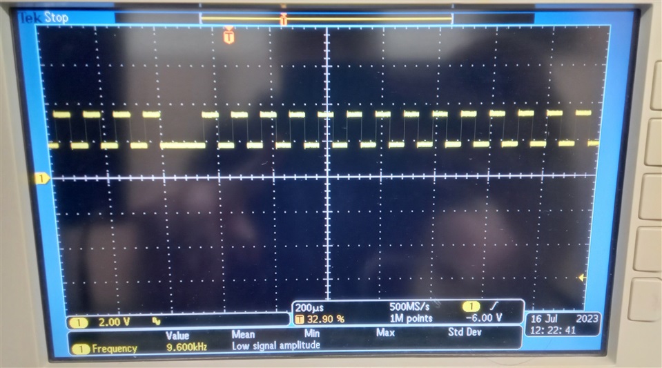
When I examine the point where I connect the two pins with an oscilloscope, I see that the voltage that should normally be 3.3V is 1.5V with an offset of about 1.8V. Where does the 3.3V voltage get this offset from? Is it because the signal amplitude is 1.5V I can't enter the RX cutout?

When I measure the RX pin at idle I see a constant 3.3V voltage.

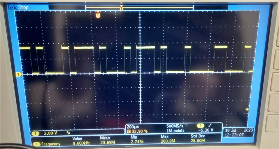
In addition, using the same code and the code change I mentioned (only turning off the enableLoopback function), when I bring the isolated rs422 output to 3.3V with the ADM2682E and connect it to the RX pin, I see the same voltage offset signal. However, when I do not connect the RX pin of the ADM2682E to the mcu, I can read the 3.3V voltage level and the rs422 signal correctly with the oscilloscope. I tried with 2 different TMS320F28379D controlCard Rev1.3, both have the same situation.

In the sample code for everything I described above; I activate the #define _LAUNCHXL_F28379D macro and just turn the loopback function on and off, no other changes.

While the RX TX pins of the mcu are connected to each other or the signal output of the ADM2682E is connected to the RX pin. In both cases when i inspect the RX pin there is offset.

When the output pin of ADM2682E is idle. 

  • Hello,

    I tested the second configuration you described(loopback disabled and jumper of F2837x TX pin connected to F2837x RX pin), and I am unable to replicate the issue you are describing where you see a 1.8 V offset and 1.5 V amplitude. What version of C2000Ware are you using? I suspect there is an issue somewhere in this block of code in the example that we may have fixed in later versions of C2000Ware:

     //
        // Setup GPIO by disabling pin locks and enabling pullups
        //
        Device_initGPIO();
    
        //
        // GPIO28 is the SCI Rx pin.
        //
        GPIO_setMasterCore(28, GPIO_CORE_CPU1);
        GPIO_setPinConfig(GPIO_28_SCIRXDA);
        GPIO_setDirectionMode(28, GPIO_DIR_MODE_IN);
        GPIO_setPadConfig(28, GPIO_PIN_TYPE_STD);
        GPIO_setQualificationMode(28, GPIO_QUAL_ASYNC);
    
        //
        // GPIO29 is the SCI Tx pin.
        //
        GPIO_setMasterCore(29, GPIO_CORE_CPU1);
        GPIO_setPinConfig(GPIO_29_SCITXDA);
        GPIO_setDirectionMode(29, GPIO_DIR_MODE_OUT);
        GPIO_setPadConfig(29, GPIO_PIN_TYPE_STD);
        GPIO_setQualificationMode(29, GPIO_QUAL_ASYNC);
    

    Thank you,

    Luke

  • Hi Luke,

    Thanks for your reply. I'm using C2000Ware 4.03.00.00.

    My code is the same as the piece of code you gave. There is no difference between them.

    Why is the SCIFFFE register 1 in my application?

    When I run the example code and nothing is connected to the Rx pin, I see the Rx pin as High on the oscilloscope. Is this normal? Considering that packet transfer starts with the transition from High to Low, it's normal actually. But could this offset be caused by pin not going from High to Low? Why do both cards have the same situation?

  • I forgot to mention above. I am running the code in debug mode. Let me summarize the process again;
    I connect the Rx and Tx pins with jumpers. I connect an oscilloscope to the point where the pins meet. I turn off the loopBack function in the sci_ex2_loopback_interrupts.c file in C2000Ware. I add the #define _LAUNCHXL_F28379D macro to the beginning of the code. I click the debug button in CCS and run the code. After running it, I see a communication signal with 1.8V offset and 1.5V amplitude at the junction of Tx and Rx pins on the oscilloscope screen.

  • When you connect the Rx and Tx pins together, does the code enter the Rx interrupt?

  • Hello,

    I have recreated your setup exactly on a F28379D Control Card, including the _LAUNCHXL_F28379D macro. I still see a normal signal from 0 to 3.3V and am able to enter the RX interrupt repeatedly.

    You're using a Control Card right? If so, why would you use the _LAUNCHXL_F28379D macro in your code?

    Thank you,

    Luke

  • Just to sanity check, could you confirm you haven't modified any oscilloscope settings that would affect the offset or amplitude of the waveform?

    Thank you,

    Luke 

  • Could you send a picture of your set up with just the control card and jumpers between the TX and RX pins?

    Thank you,

    Luke

  • Hi Luke,

    I just put a jumper between pins 76 and 78 and take measurements from this point with an oscilloscope. It is now interrupting with its own rx tx pins. But when I use ADM2682E externally, it does not interrupt. Both ADM2682E and controlCard's rx and tx pins can produce 3.3V when idle. But when I connect the Rx tx pins together or connect the corresponding pin of the ADM2682E to the rx pin of the board, the offset voltage appears. I tried with 2 different controlCards, same result. The photo shows the jumper connection type. The oscilloscope image shows the voltage of this jumper connection. The oscilloscope settings are correct.

  • C2000Ware F2837xD examples use GPIO28 and GPIO29 but the controlCard document contains the following information. I can't try right now, but would it be helpful if I changed the pins?

  • Hello,

    Yes that would be a worthwhile test to try different SCI pins. It would not explain why I do not see the issue on my side but would atleast narrow down the issue to pins 76 and 78.

    I also tested changing SW1 and SW2 and loading the program into flash. On my end, both SW1 and SW2 need to be in the upward position for the code to work, otherwise scoping the RX/TX connection results in an idle 1.9 V signal.

  • Perhaps the issue results from the actual jumper you are using. I am connecting two separate jumpers from RX and TX to a breadboard in the same row, and then connecting an oscilloscope to the breadboard.

  • I tried this way too, but the problem was not solved.

  • When I tried it with GPIO 64 GPIO 65 pins with rx and tx support, the problem disappeared. I still don't know why the offset is caused, but for now I will solve the problem like this. thanks.

  • Hello,

    Understood, glad you are able to atleast get this working on GPIO64 and GPIO 65. Let me know if you have any further questions.

    Thank you,

    Luke