This thread has been locked.

If you have a related question, please click the "Ask a related question" button in the top right corner. The newly created question will be automatically linked to this question.

TMS320F28388D: Change the Eth PHY from DP83822 to TP83825

Part Number: TMS320F28388D
Other Parts Discussed in Thread: C2000WARE

Hi,
customer uses the DP83825 instead of the DP83822 on their HW now. The C2000ware Eth examples didn't work anymore. I read that only the ID's (PHYIDR2, reg 0x3) are different. In which file do I have to change it? Are there any other things my customer has to change?

Regards, Holger

  • Hi, 

    You can take a look at the datasheets and see if there are any register differences between these two PHYs. 

    There maybe changes required to the following functions based on the differences.

    Ethernet_configureMDIO

    Ethernet_readPHYRegister 

    Ethernet_writePHYRegister

    Ethernet_configurePHYAddress

    Best Regards

    Siddharth

  • Hi Siddharth,
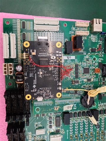
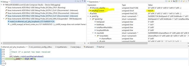
    they took a snapshot of phyRegContent of both PHY. May be the wiring is not correct.

    Regards, Holger

    DELTA TMS320f28388D Board Debug DP83825 status.pdf

    TI EVM control card Debug DP83822 status.pdf

    DP83825EVM connection with TMS320F28388D .xlsx

  • Hi, 

    Are they able to read/write to the PHY registers?

     Will get the PHY team involved in this thread to see if they have any suggestions.

    Best Regards

    Siddharth

  • Hi,

    as the phyRegContent is zero I think the wiring is not correct.

    Regards, Holger

  • Hi Holger,

    After the EVM is powered on, can we measure the CLKOUT pin and check if the PHY is functioning ?
    Can we also check if there is any clock or data noticed on RMII lines ?

    Which PHY address did you configure in the processor to communicate with the PHY on MDC/ MDIO ?

    Regards,
    Rahul

  • Hi Rahul,
    I think you mean GPIO105 and GPIO106 which are used for the MDC and MDIO in the example, right?

    Regards, Holger

  • Hi Holger,

    I was referring to the PHY address configured to the PHY.

    Which PHY address is being used to access the registers of the PHY from the Processor ?

    Regards,
    Rahul

  • Hi,
    they used PHY address 1. The DP83825 has RMII interface and the DP83822 interface. Customer forget to connect and configure RMII clock.

        //
        // Use this only for RMII Mode
        //GPIO_setPinConfig(GPIO_73_ENET_RMII_CLK);
        //

    What else has to me considered by migrating to RMII in the HW or SW?

    Regards, Holger

  • Hi Rahul,

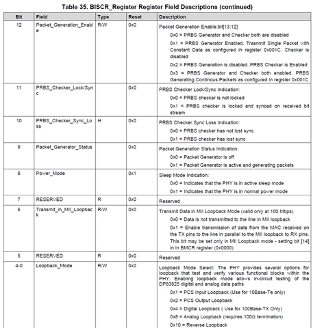
    der have register access now. But loopback test still not running at all. Enabling is now in register BISCR bit 4-0 in the DP83825.

    Regards, Holger

  • Hi Holger,

    Which RMII mode is customer looking to configure the PHY in ? Is it RMII master/ slave mode ?
    Please refer to section 7.3.10 in the datasheet:

    https://www.ti.com/lit/ds/symlink/dp83825i.pdf?ts=1691007124380&ref_url=https%253A%252F%252Fwww.ti.com%252Fproduct%252FDP83825I

    Regards,
    Rahul

  • Hi Rahul,
    he can use both modes as currently he connected the DP83825 EVM. Default is master mode.
    Attached are the both .c files he used.

    Regards, Holger

    4428.cm_common_config_c28x.c
    //#############################################################################
    //
    // FILE:   cm_common_config_c28x.c
    //
    // TITLE:  C28x Common Configurations to be used for the CM Side.
    //
    //! \addtogroup driver_example_list
    //! <h1>C28x Common Configurations</h1>
    //!
    //! This example configures the GPIOs and Allocates the shared peripherals
    //! according to the defines selected by the users.
    //!
    //
    //#############################################################################
    //
    //
    // $Copyright:
    // Copyright (C) 2022 Texas Instruments Incorporated - http://www.ti.com
    //
    // Redistribution and use in source and binary forms, with or without 
    // modification, are permitted provided that the following conditions 
    // are met:
    // 
    //   Redistributions of source code must retain the above copyright 
    //   notice, this list of conditions and the following disclaimer.
    // 
    //   Redistributions in binary form must reproduce the above copyright
    //   notice, this list of conditions and the following disclaimer in the 
    //   documentation and/or other materials provided with the   
    //   distribution.
    // 
    //   Neither the name of Texas Instruments Incorporated nor the names of
    //   its contributors may be used to endorse or promote products derived
    //   from this software without specific prior written permission.
    // 
    // THIS SOFTWARE IS PROVIDED BY THE COPYRIGHT HOLDERS AND CONTRIBUTORS 
    // "AS IS" AND ANY EXPRESS OR IMPLIED WARRANTIES, INCLUDING, BUT NOT 
    // LIMITED TO, THE IMPLIED WARRANTIES OF MERCHANTABILITY AND FITNESS FOR
    // A PARTICULAR PURPOSE ARE DISCLAIMED. IN NO EVENT SHALL THE COPYRIGHT 
    // OWNER OR CONTRIBUTORS BE LIABLE FOR ANY DIRECT, INDIRECT, INCIDENTAL, 
    // SPECIAL, EXEMPLARY, OR CONSEQUENTIAL DAMAGES (INCLUDING, BUT NOT 
    // LIMITED TO, PROCUREMENT OF SUBSTITUTE GOODS OR SERVICES; LOSS OF USE,
    // DATA, OR PROFITS; OR BUSINESS INTERRUPTION) HOWEVER CAUSED AND ON ANY
    // THEORY OF LIABILITY, WHETHER IN CONTRACT, STRICT LIABILITY, OR TORT 
    // (INCLUDING NEGLIGENCE OR OTHERWISE) ARISING IN ANY WAY OUT OF THE USE 
    // OF THIS SOFTWARE, EVEN IF ADVISED OF THE POSSIBILITY OF SUCH DAMAGE.
    // $
    //#############################################################################
    
    //
    // Included Files
    //
    #include "driverlib.h"
    #include "device.h"
    
    void main(void)
    {
    
        //
        // Initialize device clock and peripherals
        //
        Device_init();
    
        //
        // Boot CM core
        //
    #ifdef _FLASH
        Device_bootCM(BOOTMODE_BOOT_TO_FLASH_SECTOR0);
    #else
        Device_bootCM(BOOTMODE_BOOT_TO_S0RAM);
    #endif
    
        //
        // Disable pin locks and enable internal pull-ups.
        //
        Device_initGPIO();
    
    #ifdef ETHERNET
    
        // Set up EnetCLK to use SYSPLL as the clock source and set the
        // clock divider to 2.
        //
        // This way we ensure that the PTP clock is 100 MHz. Note that this value
        // is not automatically/dynamically known to the CM core and hence it needs
        // to be made available to the CM side code beforehand.
        SysCtl_setEnetClk(SYSCTL_ENETCLKOUT_DIV_2, SYSCTL_SOURCE_SYSPLL);
    
        //
        // Configure the GPIOs for ETHERNET.
        //
    
        //
        // MDIO Signals
        //
        GPIO_setPinConfig(GPIO_105_ENET_MDIO_CLK);  //MDC
        GPIO_setPinConfig(GPIO_106_ENET_MDIO_DATA); //MDIO
    
        //
        // Use this only for RMII Mode
        GPIO_setPinConfig(GPIO_73_ENET_RMII_CLK);
        //
    
        //
        //MII Signals
        //
        //GPIO_setPinConfig(GPIO_109_ENET_MII_CRS); //GPIO109
        //GPIO_setPinConfig(GPIO_110_ENET_MII_COL); //GPIO110
    
        GPIO_setPinConfig(GPIO_121_ENET_MII_TX_DATA0);
        GPIO_setPinConfig(GPIO_122_ENET_MII_TX_DATA1);
        //GPIO_setPinConfig(GPIO_123_ENET_MII_TX_DATA2); //GPIO123
        //GPIO_setPinConfig(GPIO_124_ENET_MII_TX_DATA3); //GPIO124
    
        //
        //Use this only if the TX Error pin has to be connected
        //GPIO_setPinConfig(GPIO_46_ENET_MII_TX_ERR);
        //
    
        GPIO_setPinConfig(GPIO_118_ENET_MII_TX_EN);
    
        GPIO_setPinConfig(GPIO_114_ENET_MII_RX_DATA0);
        GPIO_setPinConfig(GPIO_115_ENET_MII_RX_DATA1);
        //GPIO_setPinConfig(GPIO_116_ENET_MII_RX_DATA2); //GPIO116
        //GPIO_setPinConfig(GPIO_117_ENET_MII_RX_DATA3); //GPIO3
        GPIO_setPinConfig(GPIO_113_ENET_MII_RX_ERR);
        GPIO_setPinConfig(GPIO_112_ENET_MII_RX_DV);
    
        //GPIO_setPinConfig(GPIO_44_ENET_MII_TX_CLK);   //GPIO120
        //GPIO_setPinConfig(GPIO_111_ENET_MII_RX_CLK);  //GPIO111
    
        //
        //Power down pin to bring the external PHY out of Power down
        //
    //    GPIO_setDirectionMode(108, GPIO_DIR_MODE_OUT);
    //    GPIO_setPadConfig(108, GPIO_PIN_TYPE_PULLUP);
    //    GPIO_writePin(108,1);
    
        //
        //PHY Reset Pin to be driven High to bring external PHY out of Reset
        //
    
        GPIO_setDirectionMode(76, GPIO_DIR_MODE_OUT);
        GPIO_setPadConfig(76, GPIO_PIN_TYPE_PULLUP);
        GPIO_writePin(76,0);
        DEVICE_DELAY_US(20);
        GPIO_writePin(76,1);


    /* below Config working with TI EVM Board
        //
            // Set up EnetCLK to use SYSPLL as the clock source and set the
            // clock divider to 2.
            //
            // This way we ensure that the PTP clock is 100 MHz. Note that this value
            // is not automatically/dynamically known to the CM core and hence it needs
            // to be made available to the CM side code beforehand.
            SysCtl_setEnetClk(SYSCTL_ENETCLKOUT_DIV_2, SYSCTL_SOURCE_SYSPLL);
    
            //
            // Configure the GPIOs for ETHERNET.
            //
    
            //
            // MDIO Signals
            //
            GPIO_setPinConfig(GPIO_105_ENET_MDIO_CLK);
            GPIO_setPinConfig(GPIO_106_ENET_MDIO_DATA);
    
            //
            // Use this only for RMII Mode
            //GPIO_setPinConfig(GPIO_73_ENET_RMII_CLK);
            //
    
            //
            //MII Signals
            //
            GPIO_setPinConfig(GPIO_109_ENET_MII_CRS);
            GPIO_setPinConfig(GPIO_110_ENET_MII_COL);
    
            GPIO_setPinConfig(GPIO_75_ENET_MII_TX_DATA0);
            GPIO_setPinConfig(GPIO_122_ENET_MII_TX_DATA1);
            GPIO_setPinConfig(GPIO_123_ENET_MII_TX_DATA2);
            GPIO_setPinConfig(GPIO_124_ENET_MII_TX_DATA3);
    
            //
            //Use this only if the TX Error pin has to be connected
            //GPIO_setPinConfig(GPIO_46_ENET_MII_TX_ERR);
            //
    
            GPIO_setPinConfig(GPIO_118_ENET_MII_TX_EN);
    
            GPIO_setPinConfig(GPIO_114_ENET_MII_RX_DATA0);
            GPIO_setPinConfig(GPIO_115_ENET_MII_RX_DATA1);
            GPIO_setPinConfig(GPIO_116_ENET_MII_RX_DATA2);
            GPIO_setPinConfig(GPIO_117_ENET_MII_RX_DATA3);
            GPIO_setPinConfig(GPIO_113_ENET_MII_RX_ERR);
            GPIO_setPinConfig(GPIO_112_ENET_MII_RX_DV);
    
            GPIO_setPinConfig(GPIO_44_ENET_MII_TX_CLK);
            GPIO_setPinConfig(GPIO_111_ENET_MII_RX_CLK);
    
            //
            //Power down pin to bring the external PHY out of Power down
            //
            GPIO_setDirectionMode(108, GPIO_DIR_MODE_OUT);
            GPIO_setPadConfig(108, GPIO_PIN_TYPE_PULLUP);
            GPIO_writePin(108,1);
    
            //
            //PHY Reset Pin to be driven High to bring external PHY out of Reset
            //
    
            GPIO_setDirectionMode(119, GPIO_DIR_MODE_OUT);
            GPIO_setPadConfig(119, GPIO_PIN_TYPE_PULLUP);
            GPIO_writePin(119,1);
            */
    
    #endif
    
    #ifdef MCAN
        //
        // Setting the MCAN Clock.
        //
        SysCtl_setMCANClk(SYSCTL_MCANCLK_DIV_4);
    
        //
        // Configuring the GPIOs for MCAN.
        //
        GPIO_setPinConfig(DEVICE_GPIO_CFG_MCANRXA);
        GPIO_setPinConfig(DEVICE_GPIO_CFG_MCANTXA);
    #endif
    
    #ifdef CANA
        //
        // Configuring the GPIOs for CAN A.
        //
        GPIO_setPinConfig(DEVICE_GPIO_CFG_CANRXA);
        GPIO_setPinConfig(DEVICE_GPIO_CFG_CANTXA);
    
        //
        // Allocate Shared Peripheral CAN A to the CM Side.
        //
        SysCtl_allocateSharedPeripheral(SYSCTL_PALLOCATE_CAN_A,0x1U);
    #endif
    
    #ifdef CANB
        //
        // Configuring the GPIOs for CAN B.
        //
        GPIO_setPinConfig(DEVICE_GPIO_CFG_CANRXB);
        GPIO_setPinConfig(DEVICE_GPIO_CFG_CANTXB);
    
        //
        // Allocate Shared Peripheral CAN B to the CM Side.
        //
        SysCtl_allocateSharedPeripheral(SYSCTL_PALLOCATE_CAN_B,0x1U);
    #endif
    
    #ifdef UART
        //
        // Configure GPIO85 as the UART Rx pin.
        //
        GPIO_setPinConfig(GPIO_85_UARTA_RX);
        GPIO_setDirectionMode(85, GPIO_DIR_MODE_IN);
        GPIO_setPadConfig(85, GPIO_PIN_TYPE_STD);
        GPIO_setQualificationMode(85, GPIO_QUAL_ASYNC);
    
        //
        // Configure GPIO84 as the UART Tx pin.
        //
        GPIO_setPinConfig(GPIO_84_UARTA_TX);
        GPIO_setDirectionMode(84, GPIO_DIR_MODE_OUT);
        GPIO_setPadConfig(84, GPIO_PIN_TYPE_STD);
        GPIO_setQualificationMode(84, GPIO_QUAL_ASYNC);
    #endif
    
    #ifdef USB
    #ifdef USE_20MHZ_XTAL
        //
        // Set up the auxiliary PLL so a 60 MHz output clock is provided to the USB module.
        // This fixed frequency is required for all USB operations.
        //
        SysCtl_setAuxClock(SYSCTL_AUXPLL_OSCSRC_XTAL |
                           SYSCTL_AUXPLL_IMULT(48) |
                           SYSCTL_REFDIV(2U) | SYSCTL_ODIV(4U) |
                           SYSCTL_AUXPLL_DIV_2 |
                           SYSCTL_AUXPLL_ENABLE |
                           SYSCTL_DCC_BASE_0);
    #else
        //
        // Set up the auxiliary PLL so a 60 MHz output clock is provided to the USB module.
        // This fixed frequency is required for all USB operations.
        //
        SysCtl_setAuxClock(SYSCTL_AUXPLL_OSCSRC_XTAL |
                           SYSCTL_AUXPLL_IMULT(48) |
                           SYSCTL_REFDIV(2U) | SYSCTL_ODIV(5U) |
                           SYSCTL_AUXPLL_DIV_2 |
                           SYSCTL_AUXPLL_ENABLE |
                           SYSCTL_DCC_BASE_0);
    #endif
    
        //
        // Allocate Shared Peripheral USB to the CM Side.
        //
        SysCtl_allocateSharedPeripheral(SYSCTL_PALLOCATE_USBA, 1);
    
        GPIO_setPinConfig(GPIO_0_GPIO0);
        GPIO_setPadConfig(0, GPIO_PIN_TYPE_STD);
        GPIO_setDirectionMode(0, GPIO_DIR_MODE_OUT);
        GPIO_setMasterCore(0, GPIO_CORE_CM);
    
        //
        // Set the master core of GPIOs to CM.
        //
        GPIO_setMasterCore(42, GPIO_CORE_CM);
        GPIO_setMasterCore(43, GPIO_CORE_CM);
        GPIO_setMasterCore(46, GPIO_CORE_CM);
        GPIO_setMasterCore(47, GPIO_CORE_CM);
        GPIO_setMasterCore(120, GPIO_CORE_CM);
        GPIO_setMasterCore(121, GPIO_CORE_CM);
    
        //
        // Set the USB DM and DP GPIOs.
        //
        GPIO_setAnalogMode(42, GPIO_ANALOG_ENABLED);
        GPIO_setAnalogMode(43, GPIO_ANALOG_ENABLED);
    
        //
        // Set the direction for VBUS and ID.
        //
        GPIO_setDirectionMode(46, GPIO_DIR_MODE_IN);
        GPIO_setDirectionMode(47, GPIO_DIR_MODE_IN);
    
        //
        // Configure the Power Fault.
        //
        GPIO_setMasterCore(120, GPIO_CORE_CM);
        GPIO_setDirectionMode(120, GPIO_DIR_MODE_IN);
    
        //
        // Configure the External Power Signal Enable.
        //
        GPIO_setMasterCore(121, GPIO_CORE_CM);
    	GPIO_setDirectionMode(121, GPIO_DIR_MODE_OUT);
    	GPIO_writePin(121, 1);
    
        //
        // Set the CM Clock to run at 120MHz.
        // The CM Clock is a fractional multiple of the AUXPLL Clock (120 Mhz) from
        // which the USB Clock (60 MHz) is derived.
        //
        SysCtl_setCMClk(SYSCTL_CMCLKOUT_DIV_1, SYSCTL_SOURCE_AUXPLL);
    #endif
    }
    

    ethernet_ex2_phy_loopback.c
    //#############################################################################
    //
    // FILE:   ethernet_ex2_phy_loopback.c
    //
    // TITLE:  Ethernet Basic Transmit and Receive External (PHY) Loopback Example
    //
    //! \addtogroup driver_example_cm_list
    //! <h1> Ethernet Basic Transmit and Receive PHY Loopback </h1>
    //!
    //! This example demonstrates the steps to be followed in using the
    //! Ethernet of the Communication Manager Subsystem to initialize
    //! the Ethernet module and Configure the module in External Loop back mode
    //! the packet is looped back at external PHY.
    //! Prepares a packet to be sent, Sends the packet and reads the staticstics
    //! to check if the packet is received by the module
    //! Before running this Communication Manager code the C28x cpu1 code has to be run
    //! to configure the clocks to Communication manager
    //! and required IO pads for Ethernet module
    //!
    //! \b External \b Connections \n
    //!  This example programs the Ethernet module in External Loop back mode (at PHY)
    //! and hence needs external connection to the PHY on the MII interface and
    //! also the MDIO Pins connected to the PHY. This example assumes DP83822 PHY
    //! for the PHY configurations if a different PHY is used the sequences might change
    //! Refer to the C28x CPU1 code of ethernet_config_c28x project
    //! for which GPIOs are used for connecting to the PHY
    //!
    //! \b Watch \b Variables \n
    //!  - phyRegContent variable can be checked to know if PHY register
    //! read,write is working correctly
    //!   - stats to know if the packet is received correctly after loopback
    //! at PHY side
    //
    //#############################################################################
    //
    //
    // $Copyright:
    // Copyright (C) 2022 Texas Instruments Incorporated - http://www.ti.com
    //
    // Redistribution and use in source and binary forms, with or without 
    // modification, are permitted provided that the following conditions 
    // are met:
    // 
    //   Redistributions of source code must retain the above copyright 
    //   notice, this list of conditions and the following disclaimer.
    // 
    //   Redistributions in binary form must reproduce the above copyright
    //   notice, this list of conditions and the following disclaimer in the 
    //   documentation and/or other materials provided with the   
    //   distribution.
    // 
    //   Neither the name of Texas Instruments Incorporated nor the names of
    //   its contributors may be used to endorse or promote products derived
    //   from this software without specific prior written permission.
    // 
    // THIS SOFTWARE IS PROVIDED BY THE COPYRIGHT HOLDERS AND CONTRIBUTORS 
    // "AS IS" AND ANY EXPRESS OR IMPLIED WARRANTIES, INCLUDING, BUT NOT 
    // LIMITED TO, THE IMPLIED WARRANTIES OF MERCHANTABILITY AND FITNESS FOR
    // A PARTICULAR PURPOSE ARE DISCLAIMED. IN NO EVENT SHALL THE COPYRIGHT 
    // OWNER OR CONTRIBUTORS BE LIABLE FOR ANY DIRECT, INDIRECT, INCIDENTAL, 
    // SPECIAL, EXEMPLARY, OR CONSEQUENTIAL DAMAGES (INCLUDING, BUT NOT 
    // LIMITED TO, PROCUREMENT OF SUBSTITUTE GOODS OR SERVICES; LOSS OF USE,
    // DATA, OR PROFITS; OR BUSINESS INTERRUPTION) HOWEVER CAUSED AND ON ANY
    // THEORY OF LIABILITY, WHETHER IN CONTRACT, STRICT LIABILITY, OR TORT 
    // (INCLUDING NEGLIGENCE OR OTHERWISE) ARISING IN ANY WAY OUT OF THE USE 
    // OF THIS SOFTWARE, EVEN IF ADVISED OF THE POSSIBILITY OF SUCH DAMAGE.
    // $
    //#############################################################################
    
    //
    // Included Files
    //
    #include "driverlib_cm.h"
    #include "cm.h"
    
    //
    // Defines
    //
    #define PACKET_LENGTH 132
    
    #define ETHERNET_NO_OF_RX_PACKETS   1U
    //
    //Change this define for changing Packet buffer length
    //
    #define ETHERNET_MAX_PACKET_LENGTH 1538U
    
    
    //
    // Globals
    //
    uint8_t Ethernet_rxBuffer[ETHERNET_NO_OF_RX_PACKETS *
                              ETHERNET_MAX_PACKET_LENGTH];
    
    uint8_t pData[PACKET_LENGTH];
    uint16_t phyRegContent=0,temp=0,temp1=0;
    Ethernet_InitConfig *pInitCfg;
    Ethernet_Statistics stats;
    
    //
    // Main
    //
    void main(void)
    {
    
        Ethernet_InitInterfaceConfig initInterfaceConfig;
    
        Ethernet_Pkt_Desc pktDesc;
        uint32_t i;
        Ethernet_Handle emac_handle;
    
    
        //
        // Initialize device clock and peripherals
        //
        CM_init();
    
        //
        //Form the unicast Packet in Memory
        //
        for(i=0;i<PACKET_LENGTH/4;i++)
        {
            //
            //First 6 bytes of the packet are the MAC Destination Address
            //Bytes, the Destination and CRC shall be inserted by the hardware
            //
            if(i == 0)
                *((uint32_t *)pData + i) = 0x01020304;
            else if(i == 1)
                *((uint32_t *)pData + i)  = 0xFFFF0506;
            else
                HWREG((uint32_t *)pData +i) = 0xFFFFFFFF;
        }
    
        //
        //Select the MII interface of the module
        //
        initInterfaceConfig.ssbase = EMAC_SS_BASE;
        initInterfaceConfig.enet_base = EMAC_BASE;
        initInterfaceConfig.phyMode = ETHERNET_SS_PHY_INTF_SEL_RMII;
        initInterfaceConfig.clockSel = ETHERNET_SS_CLK_SRC_EXTERNAL;
        //
        //Assign SoC specific functions for Enabling,Disabling interrupts
        //and for enabling the Peripheral at system level
        //
        initInterfaceConfig.ptrPlatformInterruptDisable = &Platform_disableInterrupt;
        initInterfaceConfig.ptrPlatformInterruptEnable = &Platform_enableInterrupt;
        initInterfaceConfig.ptrPlatformPeripheralEnable = &Platform_enablePeripheral;
        initInterfaceConfig.ptrPlatformPeripheralReset = &Platform_resetPeripheral;
        //
        //Assign the peripheral number at the SoC
        //
        initInterfaceConfig.peripheralNum = SYSCTL_PERIPH_CLK_ENET;
        //
        //Assign the default SoC specific interrupt numbers of Ethernet interrupts
        //
        initInterfaceConfig.interruptNum[0] = INT_EMAC;
        initInterfaceConfig.interruptNum[1] = INT_EMAC_TX0;
        initInterfaceConfig.interruptNum[2] = INT_EMAC_TX1;
        initInterfaceConfig.interruptNum[3] = INT_EMAC_RX0;
        initInterfaceConfig.interruptNum[4] = INT_EMAC_RX1;
    
        pInitCfg = Ethernet_initInterface(initInterfaceConfig);
    
        //
        // Get an initial configuration of known good parameters
        //
        Ethernet_getInitConfig(pInitCfg);
        //
        //Assign the callbacks for Getting packet buffer when needed
        //Releasing the TxPacketBuffer on Transmit interrupt callbacks
        //Receive packet callback on Receive packet completion interrupt
        //
        pInitCfg->pfcbGetPacket = &Ethernet_getPacketBuffer;
        pInitCfg->pfcbFreePacket = &Ethernet_releaseTxPacketBuffer;
        pInitCfg->pfcbRxPacket = &Ethernet_receivePacketCallback;
        //
        //Assign the Buffer to be used by the Low level driver for receiving
        //Packets. This should be accessible by the Ethernet DMA
        //
        pInitCfg->rxBuffer = Ethernet_rxBuffer;
    
        //
        //The Application handle is not used by this application
        //Hence using a dummy value of 1
        //
        Ethernet_getHandle((Ethernet_Handle) 1,pInitCfg , &emac_handle);
    
        //
        //Do global Interrupt Enable
        //
        (void)Interrupt_enableInProcessor();
        //
        //Assign default ISRs
        //
        Interrupt_registerHandler(INT_EMAC_TX0, Ethernet_transmitISR);
        Interrupt_registerHandler(INT_EMAC_RX0, Ethernet_receiveISR);
        //
        //Enable the default interrupt handlers
        //
        Interrupt_enable(INT_EMAC_TX0);
        Interrupt_enable(INT_EMAC_RX0);
    
        //
        //Low Frequency
        //value of 5 for selecting the slowest possible MDIO Clock
        //Clause 22 mode
        //
        Ethernet_configureMDIO(EMAC_BASE,0,5,0);
    
        //
        //The DP83822 External PHY in Control Card
        //takes a PHY address of 1 by default
        //Configure the MDIO module to use PHY address of 0x1
        //
        Ethernet_configurePHYAddress(EMAC_BASE,1);
    
        //
        //Address 0 of PHY corresponds to Basic Mode Control Register(BMCR)
        //Read the register to know the state
        //
        //phyRegContent= Ethernet_readPHYRegister(EMAC_BASE,0);
        phyRegContent= Ethernet_readPHYRegister(EMAC_BASE,0x16);
        temp=phyRegContent;
    
        //
        //Bit 14 of BMCR configures the MII Loopback
        //
        phyRegContent |= 0x4000;
    
        //Ethernet_writePHYRegister(EMAC_BASE,0,phyRegContent);
        Ethernet_writePHYRegister(EMAC_BASE,0x16,0x4000);
    
        //
        //Read back the BMCR register to confirm that the MII Loopback
        //is configured properly
        //
        //phyRegContent= Ethernet_readPHYRegister(EMAC_BASE,0);
        phyRegContent= Ethernet_readPHYRegister(EMAC_BASE,0x16);
        temp1=phyRegContent;
    
        phyRegContent= Ethernet_readPHYRegister(EMAC_BASE,0x17);
        Ethernet_writePHYRegister(EMAC_BASE,0x17,0x00);
        phyRegContent= Ethernet_readPHYRegister(EMAC_BASE,0x17);
    
        //
        //Prepare a Packet Descriptor structure to send a packet
        //This contains a single buffer single packet
        //The Source address shall be inserted by the MAC
        //Packet CRC is auto computed by the module and appended in the packet
        //
        pktDesc.bufferLength = PACKET_LENGTH;
        pktDesc.dataOffset = 0;
        pktDesc.dataBuffer = pData;
        pktDesc.nextPacketDesc = 0;
        pktDesc.flags = ETHERNET_PKT_FLAG_SOP |ETHERNET_PKT_FLAG_EOP|ETHERNET_PKT_FLAG_SA_INS;
        pktDesc.pktChannel = ETHERNET_DMA_CHANNEL_NUM_0;
        pktDesc.pktLength = PACKET_LENGTH;
        pktDesc.validLength = PACKET_LENGTH;
        pktDesc.numPktFrags = 1;
    
        //
        //Send the packet prepared
        //
        Ethernet_sendPacket(emac_handle,&pktDesc);
    
    
        //
        //Delay for the MAC to send the packet on the wire and receive it
        //
        SysCtl_delay(3000);
    
        //
        //Read the statistics of the Module
        //
        Ethernet_getStatistics(emac_handle, &stats);
    
        //
        //Check if a packet has been received
        //
        if(!stats.rxUnicastPacketsGood)
            __asm("   bkpt #0");
    
    }


  • Hi Holger,

    If customer has RMII mode configured correctly and able to access the registers, can customer try to perform a ping test with a Link partner and check if it is working ?

    There are LEDs on the EVM to notify if the Link is available.

    Regards,

    Rahul