This thread has been locked.

If you have a related question, please click the "Ask a related question" button in the top right corner. The newly created question will be automatically linked to this question.

SM470R1B1M-HT: sm470 low power wakeup issue

Part Number: SM470R1B1M-HT

Hi Team,

There's an issue from the customer need your help:

SM470 low-power standby mode wake-up problem:

1. Set SM470 to enter standby mode and wake up through RTI interrupt. Where does the program start running after waking up? It stands to reason that the standby mode is powered off, is it equivalent to a reset?

2. It is currently detected that after exiting the low-power mode, the program can only run in the RTI interrupt, and does not restart from main(). What needs to be done in the RTI interrupt to make the program run again?

3. According to the manual, the standby mode can be woken up by SCI information, how to wake it up? Is it an SCI interrupt or does it wake up as soon as the receive buffer receives data?

Thanks & Regards,

Ben

  • Hi Ben,

      I don't have much experience and knowledge with this device. This is a rather old device. 

    1. Set SM470 to enter standby mode and wake up through RTI interrupt. Where does the program start running after waking up? It stands to reason that the standby mode is powered off, is it equivalent to a reset?

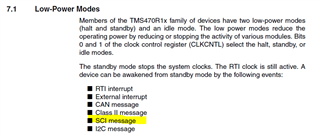
    I think after wakeup, it is supposed to restart from the instruction that entered standby mode.  A wake up should not cause a reset to the device. If you look at the below LPM description, OSC, ACLK and RTICLK are still oscillator. The RTI module is still running.

    2. It is currently detected that after exiting the low-power mode, the program can only run in the RTI interrupt, and does not restart from main(). What needs to be done in the RTI interrupt to make the program run again?

    If you already confirm that after a wake up, the processor is executing an RTI interrupt then I believe the wake up is working. Once you exit the interrupt ISR, it should resume normal operation, right? Of course, you need to clear any interrupt flag before exiting ISR. 

    3. According to the manual, the standby mode can be woken up by SCI information, how to wake it up? Is it an SCI interrupt or does it wake up as soon as the receive buffer receives data

    According to the TMS470 System module user's guide, SCI can be used to wake up the clock. I think how it works is that an high to low on RX pin will cause an wake event to the clock controller to wake up all the clocks. 

  • Hi Charles,

    Thanks for your reply. Does waking up with RTI interrupt mean that as long as the interrupt is entered, the system will be woken up? In addition, the RTI interrupt time is not set very long. I need to use RTI to delay it for a few hours, how to achieve it?

    Best Regards,

    Ben

  • Thanks for your reply. Does waking up with RTI interrupt mean that as long as the interrupt is entered, the system will be woken up?

    Hi Ben,

      Yes, that's my understanding.

     In addition, the RTI interrupt time is not set very long. I need to use RTI to delay it for a few hours, how to achieve it?

    I'm currently out of office until 8/3 without my PC. I will answer this question when I come back. 

  • Hi Ben,

    I need to use RTI to delay it for a few hours, how to achieve it?

      You need to enable the 11-bit preload that will create a 32-bit RTI counter. Refer to the below description. 

    The RTI is clocked by the RTICLK, which runs at SYSCLK frequency (see
    Section 7, Clocks, on page 43). The RTI counts RTICLK periods based upon
    the state of the CPU and the control bits CNTEN.1:0 (RTICNTEN.1:0). An
    11-bit preload value, PRELD.10:0 (RTIPCTL.10:0), provides the prescale
    value. The prescale, MOD.10:0 (RTICNTR.10:0) counts down from the
    preload to 0.


    When the prescale counts down to 0, a 21-bit counter is incremented. The
    counter, CNTR.20:0 (RTICNTR.31:11), is a count up counter. During a read
    access, both of the RTI counters (MOD.10:0 and CNTR.20:0) are read
    together in the same cycle as a single 32-bit value (RTICNTR.31:0). However,
    because the modulo M counter (MOD.10:0) is a down counter, a calculation
    needs to be performed to convert the 32-bit RTI counter value into system
    clock cycles which is given by Equation 1:
    (EQ 1)


    Where:
    M = Preload value PRELD.10:0 (RTIPCL.10:0),
    when PRELD.10:0 = 0, M = 2048


    m = Current value of MOD.10:0 (RTICNTR.10:0)
    N = Current value of CNTR.20:0 (RTICNTR.31:11)


    The real-time counter can generate three distinct interrupts off of this up
    counter:


    ❏ Tap interrupt
    ❏ Two compare interrupts (Compare1 and Compare 2)