This thread has been locked.

If you have a related question, please click the "Ask a related question" button in the top right corner. The newly created question will be automatically linked to this question.

TMS320F28379D: 3 Phase SPWM

Part Number: TMS320F28379D


Am looking to create Sinusoidal Pulse Width Modulated signal to control an AC to DC conversion using ePWM's from the F28379D MCU.

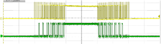
Is it possible to generate a PWM that behaves as shown below using the ePWM's modules within the F28379D?

Plot Below:

This plot shows relation of waveforms for SPWM's generated for a single phase of a 3 phase AC to DC converter.

Top Frame is plot of normalized version of PH A input signal.

  • Yielded from Inv Park Transform in controller section of conversion system

Middle Frame is plot of absolute value of "top frame" and a sawtooth (up-counter)

  • up-count would be from ePWM block

Bottom Frame is resulting SPWM and section of spwm stream set to 1 or gap in spwm for SW1 and SW2 (there would be identical SW3, SW4 and SW5, SW6 following PH B and PH C respectively)

  • Result from comparing (using "counter compare" submodule) of up-count to abs value of PH A_normalized.

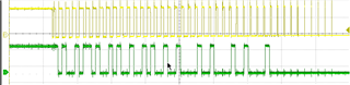
Below same as above plot but just for SW1 pwm.

Was able to generate the SPWM's without the gaps in the middle of the half cycle.

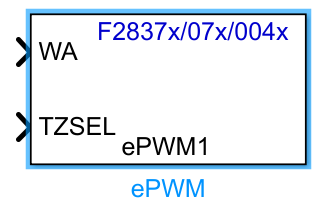
Is it possible to do this in ePWM Module in F28379D?

If it is.. what sub sections of the ePWM Module would be used to accomplish this?

Event Trigger?

Chopper?

Best,

Colin

  • Update:

    Using the Trip Zone submodule was able to get the following screenshot.

    Using a LAUNCHXL-F38279D. Set up looks like rats nest.  Not sure why so much noise on the positive half cycle. (looking into this)

    Also using 2 ePWM blocks.. one for SW1 and a second for SW2.. done because only one TZSEL per ePWM block.

    Currently looking for  alternative method:

    • Looking for cleaner result
    • Looking for way to do 2 spwm's from one ePWM block.

    Suggestions welcome.

    Best,

    Colin

  • Hi Colin,

    Looking for way to do 2 spwm's from one ePWM block.

    You can achieve two sPWMs from one ePWM block by using ePWM1A and ePWM1B. You can look into the dead band submodule to generate active high, low, high complementary, and low complementary signals. 

    For the noise, it seems to be coming from the setup, could you provide a picture of your setup? How are you scoping the signals?

    Best,

    Ryan Ma

  • Hi Ryan,

    Thanks for the input and suggestions.

    Will work on sending picture tomorrow.

    Using a 3 output sig gen for 3 phase input signals; so these are coaxial connections to a breadboard..

    Then jumper'ing breadboard wires to LAUNCHXL board header pins.  (We could get rid of the breadboard)  Am going to try and clean up and minimize wire lengths and connections soon.

    Scoping... again using the breadboard wires connected to the header pins of interest.  At one point was probing Launchxl pins directly but was worried about shorting header pins.  Picking up gnd from the breadboard, probably not the best.. prone to gnd loop issues.

    Breadboard wires image: 

    Will explore the Deadband submodule.

    Once we clean up the connections and get a tighter gnd will remeasure stuff.

    Best,

    Colin

  • Hi Colin,

    I will leave this thread open then and await your updates.

    Best,

    Ryan Ma

  • Hello Ryan,

    Below is image of the rats nest, got some more appropriate and shorter wires recently.. Plan on minimizing and re-wiring soon.

    Colin

  • Hi Colin,

    Thank you for the update, waiting on the minimization of the wires to reduce noise.

    Best,

    Ryan Ma

  • Have another related question.

    Am now trying to apply some logic gates to the output of the ePWM modules within the MCU and using a digital out GPIO to view the result.

    Referencing the images below..

    The yellow signal is using the MCU ePWM module driving actual IC logic gates.

    The green signal is using the MCU ePWM output an applying logic within the MCU then using dig out GPIO to view result.

    Yellow is the desired signal and green is a non-desired result.   

    If a GPIO can output a nice looking epwm from epwm module.. what would we have to do to get a nice signal post some logic operations on ePWM output to GPIO port. 

    right hand side of image above.

    Best,

    Colin

  • Hi Colin,

    The green signal is using the MCU ePWM output an applying logic within the MCU then using dig out GPIO to view result.

    How are you applying the "logic" within the MCU? Are you using ePWM module for this or another peripheral? What logic are you trying to apply?

    Is the yellow signal without the internal logic being applied? If so, is the ePWM module behaving as expected? 

    Best,

    Ryan Ma

  • Hi Ryan,

    Using Matlab/Simulink to generate the code for LAUNCHXL-F28379.  So we are building a model in Simulink then using embedded coder to program MCU.

    For our application we need to apply some logic to the ePWM outputs to get the pwm's needed.  Not sure we have a good grip on how to use the total functionality of the ePWM blocks but it would be really cool if we could apply logic between the ePWM outputs within the ePWM module.. example.. "ePWM1A && ePWM1B" as final output from ePWM1.  Our application... we are "and'ing" with some "or'ing" operations.

    For the green signal ("not so good signal") we are taking the MCU ePWM GPIO outputs and connecting them back into MCU via GPIO digital inputs then applying "logical operator" blocks from Simulink.  The output of logical operation is then sent to a digital output GPIO to see result. I am not sure if issue is with digital GPIO output or logic operators, leaning towards the GPIO output or the way it is configured.

    The yellow signal ("the good signal") was result of taking the MCU ePWM GPIO outputs and connecting them directly to external logic IC's on a breadboard, same logic operation as green signal, then observing it's output. This produced good and expected output of applying logical operations to ePWM outputs, although externally done.

    Best,

    Colin

  • Hi Colin,

    This sounds like a task that the CLB could help with. With type-4 ePWM you cannot AND or OR PWM outputs. However the CLB will allow you to do that if configured properly.

    If you'd like, you can create a new thread specifying how you can AND / OR PWM output signals using the CLB and we can close the current thread out since your ePWM outputs look fine without the logic applied. That way we can have the CLB expert help you configure your setup.

    Will that work with you?

    Best,

    Ryan Ma

  • Hi Ryan,

    Sure that will work.  Thanks for your help!

    Best,

    Colin