This thread has been locked.

If you have a related question, please click the "Ask a related question" button in the top right corner. The newly created question will be automatically linked to this question.

TMS320F28335: TMDSHVMTRPFCKIT F28335 debug probe reported an error

Part Number: TMS320F28335
Other Parts Discussed in Thread: TMDSDOCK28335, CONTROLSUITE, TMDSCNCD28335

Hi all,

I am using TMDSHVMTRPFCKIT with F28335 for PMSM motor control.

Errors show while external AC power is ON, the errors in Console are as follows:

C28xx: Error: (Error -1041 @ 0xFFFFFF66) The debug probe reported an error. Confirm debug probe configuration and connections, reset the debug probe, and retry the operation. (Emulation package 9.9.0.00040)
C28xx: Trouble Halting Target CPU: (Error -150 @ 0x0) One of the FTDI driver functions used during configuration returned a invalid status or an error. (Emulation package 9.9.0.00040)
C28xx: Unable to determine target status after 20 attempts
C28xx: Failed to remove the debug state from the target before disconnecting. There may still be breakpoint op-codes embedded in program memory. It is recommended that you reset the emulator before you connect and reload your program before you continue debugging

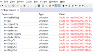
And the probe seems to be disconnected as the errors showed. The expression show as the figure below:
Also, when I try to run the code without the AC power or using a TMDSDOCK28335, it works just fine.

What could be the cause and how do I resolve this?

Btw, I can't add TMDSHVMTRPFCKIT as Part number for the thread.

  • You may take a look at the links below, and follow the guide to check the debug probe and the power supply for the controlCard.

    CCS/TMS320F28335: (Error -1135 @ 0x0) while connecting from CCS to F28335 TMDSHVMTRPFCKIT

    C2000 MCU JTAG Connectivity Debug (Rev. A)  https://www.ti.com/lit/pdf/spracf0

    And also have a look at the guide in the folder of controlSUITE below, follow the guide to set the kits to provide the power supply to the controlCard and the inverter board.

    \ti\controlSUITE\development_kits\HVMotorCtrl+PfcKit_v2.1\~Docs

  • Hi Yanming, thanks for the response.

    I forgot to mention that I have been using the same setup that works fine for almost a year and the error suddenly pops up a few days ago.

    I have gone through the links and done some checks.

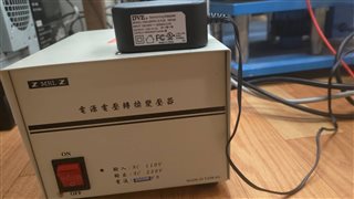
    1. For the power supplies, I am connecting an isolator for the 220VAC and the switching adpter that comes with the kit.

    Is it alright to connect them to the same extension cord or do they need to be seperated?


    2. I have re-checked all the pins that should or shouldn't be populated and they are all set as the guides.

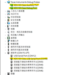
    3. In the Control Panel, I have the XDS100 as in the figure below.

     Are these correct? In the debug link you sent (the last one), there are 4 XDS110s marked and I only have 3. Is this because I have the JTAG on board? Or the emulator needs to be reprogrammed?

    4. In the figure above, when I opened the XDS100, it showed that the driver needs to be updated, therefore I did the updates. 

    After that, I try to run my program again and the motor is working as I programmed (The motor can't even work originally), however the error still exists!

    Also, I heard the sound, which is made when USB ports are connected or disconnected, when the program starts and ends. Could this information help debug the problem?

  • You may try to monitor the +5V power supply for the control Card fi there is any noise or issue on the power supply. Is there any disconnection issue if you don't connect the motor or don't spin the motor. 

  • try to monitor the +5V power supply for the control Card fi there is any noise or issue on the power supply

    I watch the leds that are supposed to light up when the +5V power supply is ON and they are lighted up, is this sufficient? Or should I use an oscilloscope? (Please guide me how for I do not have a differential probe. Thanks.)

    Is there any disconnection issue if you don't connect the motor or don't spin the motor. 

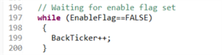
    I let "EnableFlag = 0" at the beginning, which holds the program in the start of main function aka the while loop below. 

    When I do this, no disconnection happens. Once I change "EnableFlag=1", after a second or two, the error shows and the USB ports are disconnected.

    Also, Is it allowed to disconnect the motor while I run the same program (I am now using LEVEL4 PI control for testing)?

  • When I do this, no disconnection happens. Once I change "EnableFlag=1", after a second or two, the error shows and the USB ports are disconnected.

    Do you mean that the USB emulator can be connected correctly only using +15 power supply? As mentioned above, what happens if you don't connect the motor to the kit or don't connect the kit to high voltage and just connect the +15V power supply for the controller and power module driver.?

    Also, Is it allowed to disconnect the motor while I run the same program (I am now using LEVEL4 PI control for testing)?

    Yes. You can disconnect the motor on any build level to verify if the code can be executed.

  • The code can be executed when I disconnected the motor.

    If the motor is connected, it can only work with the +15V power supply.

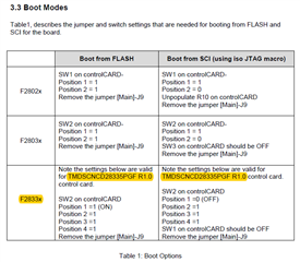
    Also, I found a boot modes setting in C:\ti\controlSUITE\development_kits\HVMotorCtrl+PfcKit_v2.1\~Docs\pdf.

    Just to make sure, when I am using an on-board JTAG with TMDSCNCD28335 R2.2, which settings should I be using? Is there different settings for TMDSCNCD28335 R2.2 and TMDSCNCD28335PGF R1.0? (There is a post for this but never been answered. Setting for ControlCARD - C2000 microcontrollers forum - C2000Tm︎ microcontrollers - TI E2E support forums)

  • If there is a JTAG debugger on the controlCARD, you may try to use the onboard JTAG debugger on controlCard, not use the onboard debugger on High Voltage Kit.

    If the motor is connected, it can only work with the +15V power supply.

    Do you mean the connection will be failed only when the high voltage supply is connected and you try to run the motor with high voltage? If yes, that mean the high voltage kit may be damaged. You may try to check if the power inverter module is damaged.

    Did you try to run the code without connecting the motor when the high voltage supply is connect to the kit?

  • Do you mean the connection will be failed only when the high voltage supply is connected and you try to run the motor with high voltage?

    Yes, this is the case! However, I tried to use a brand-new kit and the error still remains...

    Did you try to run the code without connecting the motor when the high voltage supply is connect to the kit?

    Yes, the code works fine (without disconnection).

  • What build level are you working on?

    Did you try to run the motor without loading in build level 2? What happens? 

    Did you change the value of the related variables or parameters according to your motor?

  • What build level are you working on?

    I have tried Level 2 and Level 4. They both act the same way as the discussion before (USB disconnected when motor is working with high voltage supply; code work normally when motor is not connected or there is no high voltage supply).

    Did you change the value of the related variables or parameters according to your motor?

    I have changed the QEP parameters, which can work normally for Level 4 (PI control) before.

  • Did you capture any current waveform when you try to run the motor? Is there any over current?

    I have changed the QEP parameters, which can work normally for Level 4 (PI control) before.

    What do you mean this? Run the motor in build level 4?

  • Did you capture any current waveform when you try to run the motor? Is there any over current?

    I used to monitor the currrent waveform by the code below and the graph tool.

    // ------------------------------------------------------------------------------
    // Connect inputs of the PARK module and call the park trans. macro
    // ------------------------------------------------------------------------------
    #ifdef DSP2833x_DEVICE_H
    clarke1.As=((AdcMirror.ADCRESULT1)*0.00024414-offsetA)*2*0.909; // Phase A curr.
    clarke1.Bs=((AdcMirror.ADCRESULT2)*0.00024414-offsetB)*2*0.909; // Phase B curr.
    #endif // ((ADCmeas(q12)/2^12)-offset)*2*(3.0/3.3)

    However, with the error appears, I can't get any waveform from it.

    What do you mean this? Run the motor in build level 4?

    Sorry for not answering clearly. I mean I changed the QEP parameters according to the encoder and it used to work correctly in Build Level 4.

    Also,

    I found that when I connect the 220VAC power, the F28335 control card is powered up even the 15V power switch is off. Is this a normal situation?

  • I used to monitor the currrent waveform by the code below and the graph tool.

    Did you have any current probe to monitor the motor phase current?

    Sorry for not answering clearly. I mean I changed the QEP parameters according to the encoder and it used to work correctly in Build Level 4.

    Can you run the motor well with QEP again? What changes did you make to cause the kit failed? 

    I found that when I connect the 220VAC power, the F28335 control card is powered up even the 15V power switch is off. Is this a normal situation?

    There are two options for the power supply of the controlCard, from the 15V dc power supply, or from the auxiliary power supply module using the AC power.  You may have a look at the high voltage kit user's guide and follow the kit to set the switches on the kit for the power supply.

  • Did you have any current probe to monitor the motor phase current?

    I only have a clamp meter. The current I observed from the clamp meter is about 7A max. Is this an over current?

    Can you run the motor well with QEP again? What changes did you make to cause the kit failed? 

    The error still appears with (Level 4) or without (Level 2) the QEP module. I have no idea what cause the kit to fail... 

    Would the error appear because of some changes in the codes? If so, I must have accidentally changed something. Or is it surely a hardware issue?

    You may have a look at the high voltage kit user's guide and follow the kit to set the switches on the kit for the power supply.

    Found it, it's main-J2 pin. However, populating the pin or not does not help with the error.

  • The error still appears with (Level 4) or without (Level 2) the QEP module. I have no idea what cause the kit to fail... 

    Can you try to run the original example in build level 2?  Seems like the power module or the other components are damaged if the motor is failed to run in build level 2 without load. 

  • Seems like the power module or the other components are damaged if the motor is failed to run in build level 2 without load. 

    The original level 2 fails too... but, as metioned earlier, I had tried to use a brand-new kit, which should not have any damaged components, and still got the errors.

    Also, I measured my AC power, the actual power is 242VAC, would this be a problem?

  • Did you try to run the orignal example lab within build level 2 on the new kit? Just change some of the variables according to the motor?

    Also, I measured my AC power, the actual power is 242VAC, would this be a problem?

    No. It can be up to 265VAC.

  • Did you try to run the orignal example lab within build level 2 on the new kit?

    Yes, the error still appears.

    Also, an accident just happened. I let the 220VAC and the 15V powers on for about 15 minutes without operating anything, then the lower-right corner of F28335 control card suddenly broke. This happened when I was using the new kit.

    Would this be related to my problem before?

  • Did you connect any measurement equipment like oscilloscope during run the motor with AC power supply?

    No measurement equipment is used. The kit is only connected to the motor, its encoder, and the 15V and 220VAC power supplies.

    The situation might not be the same, but I will still try to isolate my computer. Is it sufficient to just remove the ground pin? Or an isolator is a must?

    As for the other suggestion given, "removing the iso cap on the control card", I'm not sure what this corresponds to in my setup.

  • The situation might not be the same, but I will still try to isolate my computer.

    Yes. It's better to use an isolation AC source for both the computer and the high voltage kit.

    Is it sufficient to just remove the ground pin? Or an isolator is a must?

    Not enough. An isolation JTAG emulator is much better.

    As for the other suggestion given, "removing the iso cap on the control card", I'm not sure what this corresponds to in my setup.

    That depends on the controlCard if it has the CAP.

  • Hi, sorry for the delay, but we still need some days for purchasing the isolation AC source.

    At the mean time, is there any other suggestions for debugging the issue?

    Also, after the F28335 control card broke, the new kit is not working (the LEDs on the kit and replaced F28335 control card are not light up).

  • At the mean time, is there any other suggestions for debugging the issue?

    You may refer to the link mentioned above. 

    Also, after the F28335 control card broke, the new kit is not working (the LEDs on the kit and replaced F28335 control card are not light up).

    You need to check the high voltage kit is damaged as well and have to fix the damaged kit first by yourself.

    Please take a look the guides of the controlCard and high voltage kit, and follow the instruction to use these kits. And it's better to use an AC source or Power supply with over current protection for the high voltage kit during the development phase. 

  • I use the AC power in another lab and everything works, so there should be something wrong with the AC power in my lab...

  • OK. Please let's know if you have any further questions. Thanks!

  • Hi, after working successfully for a few week, the same issue appears again in the other lab... 

    Therefore, we will still need supports for resolving this issue. Thanks!

  • Please try to use an isolation AC power supply and an isolation JTAG emulator.

    What test condition you used when appeared the issue? Run the motor with a heavy load?