This thread has been locked.

If you have a related question, please click the "Ask a related question" button in the top right corner. The newly created question will be automatically linked to this question.

TMS320F28379D: Boot from power cycle

Part Number: TMS320F28379D
Other Parts Discussed in Thread: TMS320F28379S, C2000WARE

Hello, 

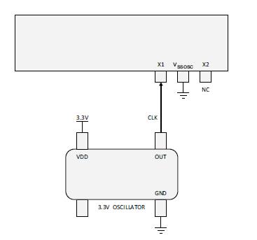
I have a custom board, and I'm using the TMS320F28379D. When I program into flash, it works fine. However, when I power cycle the board, it seems to get stuck waiting for the CLk (an external, single ended 20MHz oscillator). If I reprogram with CCS, it again works fine but get's stuck on power cycle. 

Issues:

  • MCU get's stuck on power cycle.
  • I have another board with the TMS320F28379S and it doesn't have this issue. 
  • If I heat up the MCU with a reflow station, it doesn't exhibit this issue. As it's cooling down, it takes longer and longer to boot from power cycle. (3s, 7s, 20s, ..., never boots up).

Any suggestions how to further debug this or what could be the issue? I've validated the following:

  • External CLK
  • MCU  VDD, VDDIO, etc.
  • reset pin
  • Boot mode pins (GPIO72 and GPIO84) are both pulled HIGH

Thanks so much.

  • James,

    Can you post a picture of the top side of the C2000 device; or you can also just type it in the reply if that is easier.  This will give me some manufacturing info about this unit.

    Best,

    Matthew

  • Sure thing. Here it is. 

  • James,

    Let me share this with some others, to see if there are any known issues.  I should have more info by the end of day tomm the 7th.

    Matt

  • Hi I am working with Jimmy on this and to give a little more information.  The firmware is hanging in the SysCtl_pollCpuTimer() function in the SysCtl_selectXTAL routine.  If I force the source for timer2 to use the system clock it continues on and the system comes ready.  We have not confirmed that the system clock is ok after the PLL's are enabled yet.

  • David/James,

    If you scope X1 during passing/failing do you observe the clock go missing at all?

    The code in question is checking for a missing clock before switching over to it, and if it hangs it would mean that the device isn't seeing a clock.  I suspect as we cool down we see less and less edges, until we don't see any edges.

    I thought you had a external crystal, but re-reading I see this is a canned oscillator, so there should not be any chip dependence on it starting up correctly.  I bring this up because sometimes over temperature we see the passive selection have an impact on crystal start up time, but that should not be the case here.

    If you still see your canned oscillator outputting a clock when the device hangs, will have to debug this a bit more on how this could happen.  Can you probe on the top of the X1 pin, to make sure this isn't a continuity issue(or you could press down on the X1 pin to see if it resolves things)

    Just to make sure, this is what is connected to the C2000?

    Best,

    Matthew

  • Yes this is what we have.  We did check the clock when it was in the hung mode and it seemed solid.  I am not sure that we looked at the X1 pin or not.  Jimmy is out till Thursday.  He will checkout the X1 pin then.

  • Hi Matthew,

    Please see the CLK signal below. I measured directly on the MCU pin when it hangs. I also tried pressing down on the oscillator and pin, but I didn't see it any behavior change. I'm using the DSC1001CL2-020.0000 from Microchip.

  • Hi Mathew,

    I don't know if it means anything but the X1CNT register reads 3FF according to the spec that means there is a CLK on the X1 pin.  Is that a valid assumption?

  • James/David,

    I'm still looking into this and hope to give another update later today.  X1CNT = 3FF, would indicate that there is a clock pulse on X1 pin.  I'm digging into the above functions to see if there is possibly an order of operations/or initialization that might be tripping us up.

    On the failing PCB/device; you mentioned that standalone is where we see things go bad with temperature.  Do you see any temp effect when connected to the debugger, or is that method always passing?

    Another idea, we can emulate the boot up when connected to the debugger, after launching the connection/connecting to the target on the failing board, if you go up to "scripts" and go to the emulation boot modes, and pick flash you can then do a Debug->reset and the device will go through the same boot code as in standalone.  If you can see this fail, we can start working our way toward any differences in that flow vs the load/run with the debugger.

    The GEL file may be helping us in that debug only mode, there are some aspects of the bootloader it takes care of since normally we don't execute the boot ROM when connected to the debugger/CCS(also CCS will just force start at "main" as a default as well).  Again, the above emuboot to flash will let us see what is happening as if the device was in standalone boot.

    Best,

    Matthew

  • Thanks Matthew I will give the debug->reset a try, but it fails whether the debugger is attached or not.  

  • Hi Matthew/Jimmy,

    I was playing around yesterday with this and the Debug->reset I can get the  SysCtl_pollCpuTimer() function to pass and get out of its forever loop if I change the input clock to counter2 to the system clock and I found out if I set the XTALOFF in CLKSRCCTL1 to one then back to 0.  Once I get past this function if I do the reset sequence above it will come ready multiple times after that.  But, If I single step through the SysCtl_selectXTAL function it will hang again.  I noticed that there is an errata for multiple writes to CLKSRCCTL1 can cause a hang.  Is this the hang it is referring to?

  • David,

    I'll try and look at this tonight, the E2E was down toward the end of last week so I'm catching up here.

    Best,

    Matthew

  • David,

    Inside of sysctrl.c do you see the following define(I see this at line 69 in my .c file):

    // Macro used for adding delay between 2 consecutive writes to CLKSRCCTL1
    // register.
    // Delay = 300 NOPs
    //
    #define SYSCTL_CLKSRCCTL1_DELAY  asm(" RPT #250 || NOP \n RPT #50 || NOP")

    This was added in C2000Ware V3.x and later to address the errata you mention above.   If you don't see this, or any hard coded delay in between writes to CLKSRCCTL1, then the 2nd write could get missed without the delay. 

    Along with the above can you confirm which version of C2000Ware you are using?

    Best,

    Matthew

  • Matthew,

    Thanks.  The delays are there.  I have a question about the input X2.  We were trying things to see if we could get it to come ready and one of the engineers added a 100pF cap to the X2 pin and a board which failed 100% now works 100%.  Is there any issue you can can see doing this since the spec says to leave it open?

  • David,

    Since this is a singled ended clock, X2 shouldn't come into the picture; it will/should just be the inverse of X1 in any case.

    Going back to the CPU TImer Poll that is failing; the FREE/SOFT bits below may keep the timer from counting if you are single stepping, you can try to change them to see if that makes single stepping work.

    When the code gets stalled, can you check the value in the TIM register below?  That would at least show us the current count.  The TCR register(above) will also have the overflow status bit that the CPU Timer Poll is checking.

    Best,

    Matthew

  • Hi Matthew,

    I tried the free/soft bits and didn't see any change in behavior.  Here is the output of the timer2 register.  I don't know what the reserved bit 0 means.

    CpuTimer2Regs CPUTIMER Registers
    TIM 0x000003FF CPU-Timer, Counter Register [Memory Mapped]
    MSW 0000000000000000 CPU-Timer Counter Registers High
    LSW 0000001111111111 CPU-Timer Counter Registers
    PRD 0x000003FF CPU-Timer, Period Register [Memory Mapped]
    TCR 0x0001 CPU-Timer, Control Register [Memory Mapped]
    TIF 0 CPU-Timer Interrupt Flag.
    TIE 0 CPU-Timer Interrupt Enable.
    FREE 0 Emulation modes
    SOFT 0 Emulation modes
    TRB 0 Timer reload
    TSS 0 CPU-Timer stop status bit.
    TPR 0x0000 CPU-Timer, Prescale Register [Memory Mapped]
    TPRH 0x0000 CPU-Timer, Prescale Register High [Memory Mapped]
     

  • I agree about the X2 not really doing anything.  The only thing I can think of is it might slow the edge of the clock going to the rest of the system.

  • David,

    I've got two things to try:

    1) You mentioned that toggling XTALOFF from 1 to 0 got things to work, as well as X2 cap(independently).  As we've both commented since you have a single ended clock these shouldn't matter.  I noticed that in our function to switch to an external clock we make no differentiation between a XTAL or SE Clock source. 

    If you set XTALOFF to 1 and leave it do things also work?  It is not clear to me from the description of the bit if this will "open circuit"  the path from the X1 pin to the C2000 or simply disable the internal circuit that is meant for an external X-tal to oscillate.  Assuming it is the latter, perhaps when this bit equals zero explains the weird impact of X2,etc

    2)This is more related to the undersampling of the external clock as done by the CPU Timer polling function where we get stuck.  To see if that is the issue.

    I'm copying the SelectXTAL() function below,

    2 things:

    Can you check line 36 in your code matches:

    HWREGH(CLKCFG_BASE + SYSCTL_O_AUXCLKDIVSEL) = SYSCTL_AUXPLLCLK_DIV_8;

    If this is not the setting in your code, please change it to match and re-run in the failing condition.

    If this is the same, I want to make the below change at line 57

    CPUTimer_selectClockSource(CPUTIMER2_BASE, CPUTIMER_CLOCK_SOURCE_AUX,
                                   CPUTIMER_CLOCK_PRESCALER_1);

    to

    CPUTimer_selectClockSource(CPUTIMER2_BASE, CPUTIMER_CLOCK_SOURCE_AUX,
                                   CPUTIMER_CLOCK_PRESCALER_4);

    I'm trying

    void
    SysCtl_selectXTAL(void)
    {
        uint16_t t2TCR, t2TPR, t2TPRH, t2CLKCTL;
        uint32_t t2PRD;
    
        //
        // Backup CPU timer2 settings
        //
        t2CLKCTL = HWREGH(CPUSYS_BASE + SYSCTL_O_TMR2CLKCTL);
        t2TCR = HWREGH(CPUTIMER2_BASE + CPUTIMER_O_TCR);
        t2PRD = HWREG(CPUTIMER2_BASE + CPUTIMER_O_PRD);
        t2TPR = HWREGH(CPUTIMER2_BASE + CPUTIMER_O_TPR);
        t2TPRH = HWREGH(CPUTIMER2_BASE + CPUTIMER_O_TPRH);
    
        //
        // Backup AUX clock settings
        //
        uint16_t clksrcctl2 = HWREGH(CLKCFG_BASE + SYSCTL_O_CLKSRCCTL2);
        uint16_t auxpllctl1 = HWREGH(CLKCFG_BASE + SYSCTL_O_AUXPLLCTL1);
        uint16_t auxclkdivsel = HWREGH(CLKCFG_BASE + SYSCTL_O_AUXCLKDIVSEL);
    
        //
        // Set AUX clock source to XTAL, bypass mode.
        // AUXCLK is used as the CPUTimer Clock source. SYSCLK frequency must be
        // atleast twice the frequency of AUXCLK. SYSCLK = INTOSC2(10MHz)
        // Set the AUX divider to 8. The above condition will be met for XTAL
        // frequencies up to 40MHz
        //
        EALLOW;
        HWREGH(CLKCFG_BASE + SYSCTL_O_CLKSRCCTL2) =
                (HWREGH(CLKCFG_BASE + SYSCTL_O_CLKSRCCTL2) &
                 ~(SYSCTL_CLKSRCCTL2_AUXOSCCLKSRCSEL_M)) |
                (1U << SYSCTL_CLKSRCCTL2_AUXOSCCLKSRCSEL_S);
        HWREGH(CLKCFG_BASE + SYSCTL_O_AUXPLLCTL1) = 0x0U;
        HWREGH(CLKCFG_BASE + SYSCTL_O_AUXCLKDIVSEL) = SYSCTL_AUXPLLCLK_DIV_8;
    
    
        //
        // Disable cpu timer 2 interrupt
        //
        CPUTimer_disableInterrupt(CPUTIMER2_BASE);
    
        //
        // Stop cpu timer 2 if running
        //
        CPUTimer_stopTimer(CPUTIMER2_BASE);
    
        //
        // Initialize cpu timer 2 period
        //
        CPUTimer_setPeriod(CPUTIMER2_BASE, XTAL_CPUTIMER_PERIOD);
    
        //
        // Set cpu timer 2 clock source to XTAL
        //
        CPUTimer_selectClockSource(CPUTIMER2_BASE, CPUTIMER_CLOCK_SOURCE_AUX,
                                   CPUTIMER_CLOCK_PRESCALER_1);
    
        //
        // Clear cpu timer 2 overflow flag
        //
        CPUTimer_clearOverflowFlag(CPUTIMER2_BASE);
    
        //
        // Start cpu timer 2
        //
        CPUTimer_startTimer(CPUTIMER2_BASE);
    
        EALLOW;
        //
        // Turn on XTAL
        //
        HWREGH(CLKCFG_BASE + SYSCTL_O_CLKSRCCTL1) &= ~SYSCTL_CLKSRCCTL1_XTALOFF;
        EDIS;
    
        //
        // Wait for the X1 clock to overflow cpu timer 2
        //
        SysCtl_pollCpuTimer();
    
        //
        // Select XTAL as the oscillator source
        //
        EALLOW;
        HWREGH(CLKCFG_BASE + SYSCTL_O_CLKSRCCTL1) =
        ((HWREGH(CLKCFG_BASE + SYSCTL_O_CLKSRCCTL1) &
          (~SYSCTL_CLKSRCCTL1_OSCCLKSRCSEL_M)) |
         (SYSCTL_OSCSRC_XTAL >> SYSCTL_OSCSRC_S));
        EDIS;
    
        //
        // If a missing clock failure was detected, try waiting for the cpu timer 2
        // to overflow again.
        //
        while(SysCtl_isMCDClockFailureDetected())
        {
            //
            // Clear the MCD failure
            //
            SysCtl_resetMCD();
    
            //
            // Wait for the X1 clock to overflow cpu timer 2
            //
            SysCtl_pollCpuTimer();
    
            //
            // Select XTAL as the oscillator source
            //
            EALLOW;
            HWREGH(CLKCFG_BASE + SYSCTL_O_CLKSRCCTL1) =
            ((HWREGH(CLKCFG_BASE + SYSCTL_O_CLKSRCCTL1) &
              (~SYSCTL_CLKSRCCTL1_OSCCLKSRCSEL_M)) |
             (SYSCTL_OSCSRC_XTAL >> SYSCTL_OSCSRC_S));
            EDIS;
        }
    
        //
        // Stop cpu timer 2
        //
        CPUTimer_stopTimer(CPUTIMER2_BASE);
    
        //
        // Restore Timer 2 configuration
        //
        EALLOW;
        HWREGH(CPUSYS_BASE + SYSCTL_O_TMR2CLKCTL) = t2CLKCTL;
        HWREGH(CPUTIMER2_BASE + CPUTIMER_O_TCR) = t2TCR;
        HWREG(CPUTIMER2_BASE + CPUTIMER_O_PRD) = t2PRD;
        HWREGH(CPUTIMER2_BASE + CPUTIMER_O_TPR) = t2TPR;
        HWREGH(CPUTIMER2_BASE + CPUTIMER_O_TPRH) = t2TPRH;
        HWREGH(CPUTIMER2_BASE + CPUTIMER_O_TCR) |= CPUTIMER_TCR_TRB;
    
        //
        // Restore AUX clock settings
        //
        HWREGH(CLKCFG_BASE + SYSCTL_O_CLKSRCCTL2) = clksrcctl2;
        HWREGH(CLKCFG_BASE + SYSCTL_O_AUXPLLCTL1) = auxpllctl1;
        HWREGH(CLKCFG_BASE + SYSCTL_O_AUXCLKDIVSEL) = auxclkdivsel;
        EDIS;
    
        EDIS;
    }

  • Hi Mathew,

    Where is this code from?  The library we are using doesn't have any of the AUX clock settings.  We are using C2000Ware_DigitalPower_SDK_3_03_00_00\c2000ware\driverlib\f2837xd\driverlib

    SysCtl_selectXTAL(void)
    {
    uint16_t t2TCR, t2TPR, t2TPRH, t2CLKCTL;
    uint32_t t2PRD;

    //
    // Backup CPU timer2 settings
    //
    t2CLKCTL = HWREGH(CPUSYS_BASE + SYSCTL_O_TMR2CLKCTL);
    t2TCR = HWREGH(CPUTIMER2_BASE + CPUTIMER_O_TCR);
    t2PRD = HWREG(CPUTIMER2_BASE + CPUTIMER_O_PRD);
    t2TPR = HWREGH(CPUTIMER2_BASE + CPUTIMER_O_TPR);
    t2TPRH = HWREGH(CPUTIMER2_BASE + CPUTIMER_O_TPRH);


    //
    // Disable cpu timer 2 interrupt
    //
    CPUTimer_disableInterrupt(CPUTIMER2_BASE);

    //
    // Stop cpu timer 2 if running
    //
    CPUTimer_stopTimer(CPUTIMER2_BASE);

    //
    // Initialize cpu timer 2 period
    //
    CPUTimer_setPeriod(CPUTIMER2_BASE, XTAL_CPUTIMER_PERIOD);

    //
    // Set cpu timer 2 clock source to XTAL
    //
    CPUTimer_selectClockSource(CPUTIMER2_BASE, CPUTIMER_CLOCK_
    CPUTIMER_CLOCK_PRESCALER_1);

    //
    // Clear cpu timer 2 overflow flag
    //
    CPUTimer_clearOverflowFlag(CPUTIMER2_BASE);

    //
    // Start cpu timer 2
    //
    CPUTimer_startTimer(CPUTIMER2_BASE);

    EALLOW;
    //
    // Turn on XTAL
    //
    HWREGH(CLKCFG_BASE + SYSCTL_O_CLKSRCCTL1) &= ~SYSCTL_CLKSR
    EDIS;

    //
    // Wait for the X1 clock to overflow cpu timer 2
    //
    SysCtl_pollCpuTimer();

    //
    // Select XTAL as the oscillator source
    //
    EALLOW;
    HWREGH(CLKCFG_BASE + SYSCTL_O_CLKSRCCTL1) =
    ((HWREGH(CLKCFG_BASE + SYSCTL_O_CLKSRCCTL1) &
    (~SYSCTL_CLKSRCCTL1_OSCCLKSRCSEL_M)) |
    ((uint32_t)SYSCTL_OSCSRC_XTAL >> SYSCTL_OSCSRC_S));
    EDIS;

    //
    // If a missing clock failure was detected, try waiting fo
    // to overflow again.
    //
    while(SysCtl_isMCDClockFailureDetected())
    {
    //
    // Clear the MCD failure
    //
    SysCtl_resetMCD();

    //
    // Wait for the X1 clock to overflow cpu timer 2
    //
    SysCtl_pollCpuTimer();

    //
    // Select XTAL as the oscillator source
    //
    EALLOW;
    HWREGH(CLKCFG_BASE + SYSCTL_O_CLKSRCCTL1) =
    ((HWREGH(CLKCFG_BASE + SYSCTL_O_CLKSRCCTL1) &
    (~SYSCTL_CLKSRCCTL1_OSCCLKSRCSEL_M)) |
    ((uint32_t)SYSCTL_OSCSRC_XTAL >> SYSCTL_OSCSRC_S));
    EDIS;
    }

  • David,

    This code is from our general C2000Ware installation. 

    For your example please change

    CPUTimer_selectClockSource(CPUTIMER2_BASE, CPUTIMER_CLOCK_
    CPUTIMER_CLOCK_PRESCALER_1);

    to

    CPUTimer_selectClockSource(CPUTIMER2_BASE, CPUTIMER_CLOCK_
    CPUTIMER_CLOCK_PRESCALER_4);

    Best,

    Matthew

  • Hi Matthew,

    Sorry that didn't do anything to get past the hang.

  • David,

    Can you replace your "SelectXTAL()" Function with the one I C/P above? It looks like it saves/restores everything, so I don't think this should impact any code downstream.

    I would like to confirm that AUXCLK use does/does not fix this either.  While it seems that either prescale(either TIMER2CLK or AUXCLK) should work for what we want to do, since AUXCLK was used in the driver I would like to ensure there is not something specific to this path.  There may be a reason that the extra code was written for AUXCLK path, even if it is not clear to me the difference in either path.

    I think we are still undersampling the external clock somehow, I think that fits into the temperature aspect you are seeing, as well as the XCLKOFF behavior.

    Best,
    Matthew

  • Hi Matthew,

    That seems to do the trick.  Will do some more testing over multiple boards to see how it does.  I would also like to understand why it works.  

    Thanks for all the help.

    Dave Gregg

  • Dave,

    I'll be confirming the reason that our initial PRESCALE didn't work in parallel.  Will look for your update.

    Best,

    Matthew

  • Hi Matthew,  I have tried this on several boards (4-5) and they are all working great.   Thanks for the help.  Please keep me up to date on the PRESCALE.

  • David,

    Good timing on the reply, just got through an extended email chain with our design team on this.

    The CPUTIMERPRESCALE register bits that control the Timer Prescale of its supplied clock are not implemented as a true clock divider, but as a counter to achieve a "prescaled" counter.  However, because of this, if the input clock is > than SYSCLK then we run the risk of not actually detecting the input clock as high or at least not reliably detecting a high or low for each rising edge of the internal SYSCLK.

    This is what was happening in your system, the reason we saw a temperature dependence is because at this point in the code SYSCLK is derived from the internal 0-pin oscillator (INTOSC2) which has a temperature co-efficient that is quite large compared to a pure X-tal derived clock source.  So as you raise/lowered your device temperature we would change the frequency relationship between SYSCLK and the clock you are providing to X1 pin.

    Now, the AUXCLKIN path, and more importantly its divider, is a true clock divider, which will slow the input frequency of the signal on X1 before it enters the timer. SYSCLK is still the owning clock domain, but now the X1 clock path is slower than SYSCLK, so that no matter the shift over temperature we always sample it correctly.

    There are some references to this in the DS, but they are not clear on the above implementation of the PRESCALE bit we were trying to use the first go round.

    Thanks for your patience here, and glad things are working as they should in your system.

    Best,
    Matthew