Other Parts Discussed in Thread: C2000WARE
Hello,
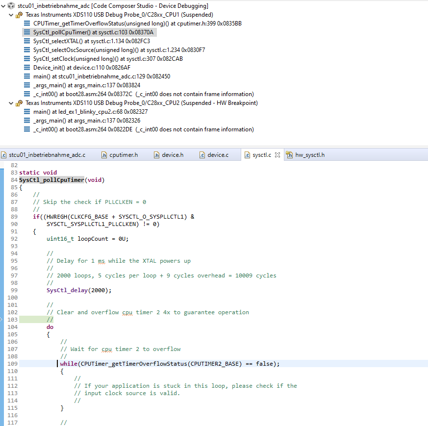
I've got the following problem. My cpu gets stuck at startup. It stucks while waiting for the CPUTimer2 to overrun (CPUTimer_getTimerOverflowStatus(CPUTIMER2_BASE)).
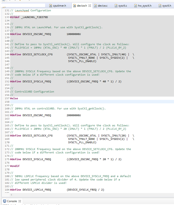
The Problem does not exist if I change the oscillator source from the external oscillator (xtal) to the internal oscillator intosc2.
I'm doing this by changing the #define DEVICE_SETCLOCK_CFG in device.h.
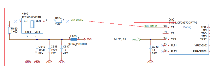
Are there any suggestions to this problem? There is a 20MHz oscillator connected to x1 on my hardware.