Other Parts Discussed in Thread: C2000WARE
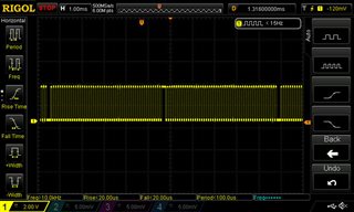
IN THE BELOW STATED PROGRAM I HAD INTRODUCED AN EPWM INTERRUPT. IN THAT TO CHECK THE STATUS I TOGGLED A GPIO PIN. ON OBSERVING THE WAVEFORM AT TWO INSTANTS THE PULSES ARE MISSING. i AM UNABLE TO FIND OUT THE REAL CAUSE OF THE SAME. HEREWITH I AM SHARING THE CODE AND THE WAVEFORM OF THE SAME FOR YOUR REFERENCE.
//
// Included Files
//
#include "driverlib.h"
#include "device.h"
#include "TMS320_PWM.h"
#include "TMS320_ADC.h"
#include "LCH.h"
#define _IQsat(A, pos, neg ) __IQsat(A, pos, neg )
//
// Globals
//
uint16_t cpuTimer0IntCount;
uint16_t cpuTimer1IntCount;
uint16_t cpuTimer2IntCount;
// PHASE AND BATTERY VOLTAGE DEFINE
/*unsigned int phase_val,phase = 0;
unsigned int phase_val1,phase1 = 0,phase12 = 0;
float ki = 200, kp= 0.0005;
unsigned int SETPOINT = 130;
long error;
long error_prev;
long BAT_ACTV;
long BAT_ACTV1,BAT_ACTV2;
long BATT_V_INST1;
long BATT_V_INST2;
long BATT_V_INST3;
long BATT_AVG_CNT;
long BATT_V;
float integral, pi_out, Umax=2400, x1, Umin=-2400;
float y1;*/
unsigned int delay =0;
// BATTERY VOLTAGE FUNCTION
void battery_voltage(void);
void inputbattery_voltage(void);
// Function Prototypes
__interrupt void cpuTimer0ISR(void);
__interrupt void cpuTimer1ISR(void);
__interrupt void cpuTimer2ISR(void);
__interrupt void epwm1ISR(void);
__interrupt void epwm2ISR(void);
void initCPUTimers(void);
void configCPUTimer(uint32_t, float, float);
// GPIO PIN CONFIGURATION - PWM1A,1B, PWM2A,2B, PWM 3A,3B, PWM4A,4B, PWM6A,6B
#define GPIO_PIN_EPWM1_A 0
#define myEPWM1_EPWMA_GPIO 0
#define myEPWM1_EPWMA_PIN_CONFIG GPIO_0_EPWM1_A
#define GPIO_PIN_EPWM1_B 1
#define myEPWM1_EPWMB_GPIO 1
#define myEPWM1_EPWMB_PIN_CONFIG GPIO_1_EPWM1_B
#define GPIO_PIN_EPWM2_A 2
#define myEPWM2_EPWMA_GPIO 2
#define myEPWM2_EPWMA_PIN_CONFIG GPIO_2_EPWM2_A
#define GPIO_PIN_EPWM2_B 3
#define myEPWM2_EPWMB_GPIO 3
#define myEPWM2_EPWMB_PIN_CONFIG GPIO_3_EPWM2_B
#define GPIO_PIN_EPWM3_A 4
#define myEPWM3_EPWMA_GPIO 4
#define myEPWM3_EPWMA_PIN_CONFIG GPIO_4_EPWM3_A
#define GPIO_PIN_EPWM3_B 5
#define myEPWM3_EPWMB_GPIO 5
#define myEPWM3_EPWMB_PIN_CONFIG GPIO_5_EPWM3_B
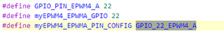
#define GPIO_PIN_EPWM4_A 22
#define myEPWM4_EPWMA_GPIO 22
#define myEPWM4_EPWMA_PIN_CONFIG GPIO_22_EPWM4_A
#define GPIO_PIN_EPWM4_B 7
#define myEPWM4_EPWMB_GPIO 7
#define myEPWM4_EPWMB_PIN_CONFIG GPIO_7_EPWM4_B
#define GPIO_PIN_EPWM6_A 10
#define myEPWM6_EPWMA_GPIO 10
#define myEPWM6_EPWMA_PIN_CONFIG GPIO_10_EPWM6_A
#define GPIO_PIN_EPWM6_B 11
#define myEPWM6_EPWMB_GPIO 11
#define myEPWM6_EPWMB_PIN_CONFIG GPIO_11_EPWM6_B
#define GPIO_PIN_8 8
#define GPIO8_CONFIG GPIO_8_GPIO8
// LCD DISPLAY
//
// Main
//
void main(void)
{
// Initializes device clock and peripherals
Device_init();
// Initializes PIE and clears PIE registers. Disables CPU interrupts.
Interrupt_initModule();
// Initializes the PIE vector table with pointers to the shell Interrupt
// Service Routines (ISR).
Interrupt_initVectorTable();
// ISRs for each CPU Timer interrupt
Interrupt_register(INT_TIMER0, &cpuTimer0ISR);
Interrupt_register(INT_TIMER1, &cpuTimer1ISR);
Interrupt_register(INT_TIMER2, &cpuTimer2ISR);
//
// Assign the interrupt service routines to ePWM interrupts
//
Interrupt_register(INT_EPWM1, &epwm1ISR);
Interrupt_register(INT_EPWM2, &epwm2ISR);
// Initializes the Device Peripheral. For this example, only initialize the
// Cpu Timers.
initCPUTimers();
// Configure CPU-Timer 0, 1, and 2 to interrupt every 1, 2, 4 seconds: 1, 2, 4 Period respectively (in uSeconds)
configCPUTimer(CPUTIMER0_BASE, DEVICE_SYSCLK_FREQ, 100);
configCPUTimer(CPUTIMER1_BASE, DEVICE_SYSCLK_FREQ, 100);
configCPUTimer(CPUTIMER2_BASE, DEVICE_SYSCLK_FREQ, 100);
// To ensure precise timing, use write-only instructions to write to the entire register. Therefore, if any of the configuration bits are changed in configCPUTimer and initCPUTimers, the below settings must also
// be updated.
CPUTimer_enableInterrupt(CPUTIMER0_BASE);
CPUTimer_enableInterrupt(CPUTIMER1_BASE);
CPUTimer_enableInterrupt(CPUTIMER2_BASE);
// Enables CPU int1, int13, and int14 which are connected to CPU-Timer 0, CPU-Timer 1, and CPU-Timer 2 respectively. Enable TINT0 in the PIE: Group 1 interrupt 7
Interrupt_enable(INT_TIMER0);
Interrupt_enable(INT_TIMER1);
Interrupt_enable(INT_TIMER2);
//
// Enable ePWM interrupts
//
Interrupt_disable(INT_EPWM1);
Interrupt_enable(INT_EPWM2);
// Starts CPU-Timer 0, CPU-Timer 1, and CPU-Timer 2.
CPUTimer_startTimer(CPUTIMER0_BASE);
CPUTimer_startTimer(CPUTIMER1_BASE);
CPUTimer_startTimer(CPUTIMER2_BASE);
// EPWM FUNCTION INITIALISATION AND SYNC INITIALISATION
initEPWM();
myINPUTXBARINPUT0_init();
SYNC_init();
// ADC INITIALISATION AND EPWM_ADC INITIALISATION
ADC_Board_init();
initEPWM_ADC();
// PIN CONFIGURATION FOR PWM1A,1B, PWM2A,2B, PWM3A,3B, PWM4A,4B, PWM 6A,6B
//
GPIO_setPinConfig(GPIO_0_EPWM1_A);
GPIO_setPadConfig(myEPWM1_EPWMA_GPIO, GPIO_PIN_TYPE_STD);
GPIO_setQualificationMode(myEPWM1_EPWMA_GPIO, GPIO_QUAL_SYNC);
GPIO_setPinConfig(GPIO_1_EPWM1_B);
GPIO_setPadConfig(myEPWM1_EPWMB_GPIO, GPIO_PIN_TYPE_STD);
GPIO_setQualificationMode(myEPWM1_EPWMB_GPIO, GPIO_QUAL_SYNC);
GPIO_setPinConfig(GPIO_2_EPWM2_A);
GPIO_setPadConfig(myEPWM2_EPWMA_GPIO, GPIO_PIN_TYPE_STD);
GPIO_setQualificationMode(myEPWM2_EPWMA_GPIO, GPIO_QUAL_SYNC);
GPIO_setPinConfig(GPIO_3_EPWM2_B);
GPIO_setPadConfig(myEPWM2_EPWMB_GPIO, GPIO_PIN_TYPE_STD);
GPIO_setQualificationMode(myEPWM2_EPWMB_GPIO, GPIO_QUAL_SYNC);
GPIO_setPinConfig(GPIO_4_EPWM3_A);
GPIO_setPadConfig(myEPWM3_EPWMA_GPIO, GPIO_PIN_TYPE_STD);
GPIO_setQualificationMode(myEPWM3_EPWMA_GPIO, GPIO_QUAL_SYNC);
GPIO_setPinConfig(GPIO_5_EPWM3_B);
GPIO_setPadConfig(myEPWM3_EPWMB_GPIO, GPIO_PIN_TYPE_STD);
GPIO_setQualificationMode(myEPWM3_EPWMB_GPIO, GPIO_QUAL_SYNC);
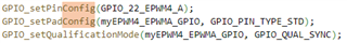
GPIO_setPinConfig(GPIO_22_EPWM4_A);
GPIO_setPadConfig(myEPWM4_EPWMA_GPIO, GPIO_PIN_TYPE_STD);
GPIO_setQualificationMode(myEPWM4_EPWMA_GPIO, GPIO_QUAL_SYNC);
GPIO_setPinConfig(GPIO_7_EPWM4_B);
GPIO_setPadConfig(myEPWM4_EPWMB_GPIO, GPIO_PIN_TYPE_STD);
GPIO_setQualificationMode(myEPWM4_EPWMB_GPIO, GPIO_QUAL_SYNC);
//EPWM6 PIN CONFIGURATION
GPIO_setPinConfig(GPIO_10_EPWM6_A);
GPIO_setPadConfig(myEPWM6_EPWMA_GPIO, GPIO_PIN_TYPE_STD);
GPIO_setQualificationMode(myEPWM6_EPWMA_GPIO, GPIO_QUAL_SYNC);
GPIO_setPinConfig(GPIO_11_EPWM6_B);
GPIO_setPadConfig(myEPWM6_EPWMB_GPIO, GPIO_PIN_TYPE_STD);
GPIO_setQualificationMode(myEPWM6_EPWMB_GPIO, GPIO_QUAL_SYNC);
// EPWM INITIALLISATION
initEPWM();
// ADC B4 PIN CONFIGURATION
GPIO_setPinConfig(GPIO_236_GPIO236); // Analog PinMux for B4
GPIO_setAnalogMode(236, GPIO_ANALOG_ENABLED);
// ADC C3 PIN CONFIGURATION
GPIO_setPinConfig(GPIO_245_GPIO245); // Analog PinMux for C3
GPIO_setAnalogMode(245, GPIO_ANALOG_ENABLED);
// ADC A3 PIN CONFIGURATION (CURRENT SENSING INPUT)
GPIO_setPinConfig(GPIO_229_GPIO229); // Analog PinMux for A3
GPIO_setAnalogMode(229, GPIO_ANALOG_ENABLED);
// ADC A10 PIN CONFIGURATION (CURRENT SENSING OUTPUT)
GPIO_setPinConfig(GPIO_230_GPIO230); // Analog PinMux for A10
GPIO_setAnalogMode(230, GPIO_ANALOG_ENABLED);
// LCD DISPLAY
GPIO_setPadConfig(data, GPIO_PIN_TYPE_STD);
GPIO_setDirectionMode(data, GPIO_DIR_MODE_OUT);
GPIO_setPadConfig(clock, GPIO_PIN_TYPE_STD);
GPIO_setDirectionMode(clock, GPIO_DIR_MODE_OUT);
GPIO_setPadConfig(LCD_Dir, GPIO_PIN_TYPE_STD);
GPIO_setDirectionMode(LCD_Dir, GPIO_DIR_MODE_OUT);
// GPIO PIN 8 IS SET AS OUTPUT
GPIO_setPadConfig(8, GPIO_PIN_TYPE_STD); // Enable pullup on GPIO8
GPIO_setPinConfig(GPIO_8_GPIO8); // GPIO8 = GPIO8
GPIO_setDirectionMode(8, GPIO_DIR_MODE_OUT);
GPIO_writePin(8,1);
// Enable Global Interrupt (INTM) and realtime interrupt (DBGM)
EINT;
ERTM;
// IDLE loop. Just sit and loop forever (optional)
while(1)
{
}
}
__interrupt void epwm1ISR(void)
{
// Clear INT flag for this timer
//
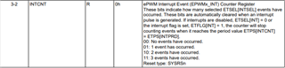
EPWM_clearEventTriggerInterruptFlag(myEPWM1_BASE);
//
// Acknowledge interrupt group
//
Interrupt_clearACKGroup(INTERRUPT_ACK_GROUP3);
}
//
// epwm2ISR - ePWM 2 ISR
//
__interrupt void epwm2ISR(void)
{ GPIO_togglePin(8);
if(x == 1)
{ EPWM_setCounterCompareValue(myEPWM3_BASE, EPWM_COUNTER_COMPARE_A, 0);
EPWM_setCounterCompareValue(myEPWM4_BASE, EPWM_COUNTER_COMPARE_A, 0);
EPWM_setCounterCompareValue(myEPWM2_BASE, EPWM_COUNTER_COMPARE_A, 0);
EPWM_setCounterCompareValue(myEPWM6_BASE, EPWM_COUNTER_COMPARE_A, 0);
x=0;
}
else {EPWM_setCounterCompareValue(myEPWM3_BASE, EPWM_COUNTER_COMPARE_A, duty);
EPWM_setCounterCompareValue(myEPWM4_BASE, EPWM_COUNTER_COMPARE_A, duty);
EPWM_setCounterCompareValue(myEPWM2_BASE, EPWM_COUNTER_COMPARE_A, duty);
EPWM_setCounterCompareValue(myEPWM6_BASE, EPWM_COUNTER_COMPARE_A, duty);
x=1;
}
//
// Clear INT flag for this timer
//
EPWM_clearEventTriggerInterruptFlag(myEPWM2_BASE);
//
// Acknowledge interrupt group
//
Interrupt_clearACKGroup(INTERRUPT_ACK_GROUP3);
}
// End of File