This thread has been locked.

If you have a related question, please click the "Ask a related question" button in the top right corner. The newly created question will be automatically linked to this question.

TMS320F28335: TMS320F28335

Part Number: TMS320F28335

Hi guys, is there any way to turn on/off a GPIO signal at the dead-time period of PWM? I used the ePWM event trigger of TI DSP 28335, but it seems it doesn't work well. Do you guys have any experience with it? Thank you very much.
  • Hi Trung,

    When are you setting your event trigger? Could you please share information on when the event trigger ISR is occurring as well as the contents of the ISR?

    Regards,

    Allison

  • Sure, let's say I have two PWM modules: 4A, B and 5A, B, and a gpio signal to determine whether both work together or one works. For example, if the gpio signal is low, both PWM modules 4 and 5 work, if the gpio signal is high, only PWM module 4 works. The gpio signal is based on a reading adc value.

    This is the setting for PWM4

    void PWM4_SET(void){
    //Time_Base(TB)
    EPwm4Regs.TBSTS.all = 0;
    EPwm4Regs.TBPHS.half.TBPHS = 0;
    EPwm4Regs.TBCTL.bit.PHSEN = TB_ENABLE;
    EPwm4Regs.TBCTR = 0;

    EPwm4Regs.TBCTL.bit.CTRMODE = TB_COUNT_UP;
    EPwm4Regs.TBCTL.bit.PRDLD = TB_IMMEDIATE;
    EPwm4Regs.TBCTL.bit.SYNCOSEL = TB_CTR_ZERO;
    //EPwm1Regs.TBCTL.bit.SWFSYNC = 0;
    EPwm4Regs.TBCTL.bit.HSPCLKDIV = TB_DIV1;
    EPwm4Regs.TBCTL.bit.CLKDIV = TB_DIV1;

    //COMP
    EPwm4Regs.TBPRD = TBPRD;
    EPwm4Regs.CMPCTL.bit.LOADAMODE = CC_LD_DISABLE;
    EPwm4Regs.CMPCTL.bit.LOADBMODE = CC_LD_DISABLE;
    EPwm4Regs.CMPCTL.bit.SHDWAMODE = CC_IMMEDIATE;
    EPwm4Regs.CMPCTL.bit.SHDWBMODE = CC_IMMEDIATE;
    EPwm4Regs.CMPA.half.CMPA = TBPRD / 2;
    EPwm4Regs.CMPB = TBPRD;


    EPwm4Regs.AQCTLA.bit.CAU = AQ_CLEAR;
    EPwm4Regs.AQCTLA.bit.ZRO = AQ_SET;

    EPwm4Regs.DBCTL.bit.OUT_MODE = DB_FULL_ENABLE;
    EPwm4Regs.DBCTL.bit.POLSEL = DBA_RED_DBB_FED;
    EPwm4Regs.DBRED = TBPRD/2;
    EPwm4Regs.DBFED = TBPRD/2;

    //Trip-Zone(TZ)
    EPwm4Regs.TZSEL.all = 1;
    EPwm4Regs.TZCTL.all = 0;
    EPwm4Regs.TZEINT.all = 0;
    EPwm4Regs.TZFLG.all = 0;
    EPwm4Regs.TZFRC.all = 0;

    EPwm4Regs.ETSEL.all = 0;
    EPwm4Regs.ETFLG.all = 0;
    EPwm4Regs.ETCLR.all = 0;
    EPwm4Regs.ETFRC.all = 0;

    //ET for PWM4
    EPwm4Regs.ETSEL.bit.INTEN = 1;
    EPwm4Regs.ETPS.bit.INTPRD = 1;
    EPwm4Regs.ETSEL.bit.INTSEL = 1;


    EPwm4Regs.PCCTL.all = 0;
    }

    This is the code for turning on or off the GPIO signal, I used an Event trigger of PWM4 to turn off the GPIO signal.

    void Mode_sw(void){
    if(Iadc > 1.66 && Operation == 3){


    EPwm4Regs.ETCLR.bit.INT = 1;
    PieCtrlRegs.PIEACK.all = PIEACK_GROUP3;
    }
    else if(Iadc < 1.59 && Operation == 1){
    Operation = 3;
    }
    else{
    Operation = Operation;
    }
    }

    This is the ET interrupt subroutine:

    interrupt void sw_et_isr(void){
    if(EPwm4Regs.ETFLG.bit.INT == 1){
    Operation = 1;
    OperationGate();
    }
    else{
    EPwm4Regs.ETCLR.bit.INT = 1;
    PieCtrlRegs.PIEACK.all = PIEACK_GROUP3;
    }
    }

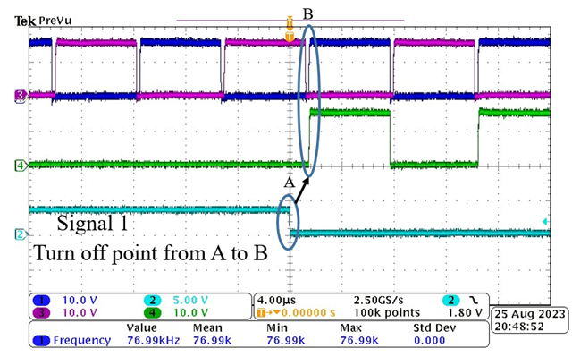
    This is the waveform signal I get

  • Hi Trung,

    Why is the RED on EPWM4A and FED on EPWM4B = TBPRD/2 for both in your setup? The delays would then line up with each other, cancelling out the dead band time. To clarify, does the below image align with what you are trying to produce?

    Is the GPIO signal going low within the dead time period, or at a particular edge of the PWM signal?

    If you could also please clarify the names of the signals in your waveform screenshots, that would help.

    Regards,

    Allison

  • Hi Allison,

    My project is controlling a system using a frequency control method so I used TBPRD to update the switching frequency. I have two operation modes ("1" and "3") needed to be switched according to the ADC value "Iadc".
    Mode 1 (Iadc > 1.66): GPIO 26 is low and all PWM 4A, 4B, 5A, 5B work.
    Mode 3 (Iadc < 1.59): GPIO 26 is high and PWM 4A, 4B work, but PWM 5A, 5B is turned off. (by setting DBRED and DBFED = TBPRD/2 +1)
    I want to switch mode at the dead-time period of PWM 4A, 4B so I used Event trigger interrupt of PWM4 by setting CTRU=CMPB.

    (My PWM setting is for Time-Base count-up mode)

    My problem is the GPIO26 signal not going low within the dead time period, or at a particular edge of the PWM signal. The attached picture is the transition from Mode 3 to Mode 1.

    Regards

  • Hi Trung, 

    Is it just the GPIO output that is not following what you are trying to set up? Or is it also the EPWM4 or EPWM5 outputs that are undesirable?

    Also, is there a reason why the GPIO toggle needs to be perfectly in sync with the dead time period- is there some other device reading this GPIO? Or is it for debugging purposes to show when the mode has been changed? Using an ISR will introduce some expected delay between the event trigger and GPIO toggle as well.

    Regards,

    Allison

  • Hi Allison,

    The GPIO output is not following what I am trying to set up. I suspected I put so many things in the ET ISR subroutine. The GPIO toggle needs to be perfectly in sync with the dead time period because it is used to control a power switch that needs to be turned off in the dead time period of PWM4.
    As you mentioned, "Using an ISR will introduce some expected delay between the event trigger and GPIO toggle as well". Is there any way to overcome this issue?
    By the way, I used EPwmxRegs.TBPRD = TBPRD (x=4,5) to control the frequency of EPwm4, EPwm5. If I want to turn off EPwm5 when the GPIO is high and turn it back on when the GPIO is low. What is the best way to do it? Currently, I turn EPwm5 off by setting DBRED and DBFED to a value that is larger than the duty of EPwm5.

    Regards,

  • Hi Trung,

    The best way to eliminate the delay would be to avoid utilizing the ISR altogether, otherwise there is always some inherent delay introduced here. 

    If you want to sync EPWM5 turning off with a GPIO toggling low, you could use a third EPWM module as the GPIO. This third EPWM could have an action qualifier that is configured at the same place you define "mode 1" and "mode 3". For mode 3 you could configure the action qualifier to occur on CTR = 0 to set the EPWM high, and then for mode 1 you could configure the action qualifier to occur on the same CMPA as your other EPWM to set it low. In this way, your EPWM5 and the GPIO/EPWM mode changes would be synced. Let me know if you have further inquiries here.

    Regards,

    Allison

  • Thank you Allison, I will give it a try and update my progress