This thread has been locked.

If you have a related question, please click the "Ask a related question" button in the top right corner. The newly created question will be automatically linked to this question.

TIEVM-HV-1PH-DCAC: How to setup the board/soft to use it in Grid Sync

Part Number: TIEVM-HV-1PH-DCAC
Other Parts Discussed in Thread: TMS320F28379D, TIDM-HV-1PH-DCAC, POWERSUITE

Hello everyone,

We had successfully setup the board TIEVM-HV-1PH-DCAC with TMS320F28379D in open loop with 100ohm load (as explain on the datasheet), it worked. 

Now, we are trying to perform grid sync to inject power. So we are modify GUI option "INCR_BUILD" to "Closed Current Loop & Grid Sync" ; Other options seem's to be good. At our first try, the circuit breaker tripped. 

Any idea what we miss ? 

Edit :

We following instruction on :"Design Guide: TIDM-HV-1PH-DCAC Grid Connected Inverter Reference Design"

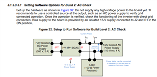
Chapter : "3.1.2.3.3.1 Setting Software Options for Build 2: AC Check" 

Thanks in advance, 

Jordan.C

  • Hello Jordon

    Are you making sure you have provided enough DC voltage?

    Thanks

    Amir

  • Hello,

    In our case we are injecting 360v DC. I think it's enought.

    Thanks,

    Jordan

  • Hello Jordon

    At our first try, the circuit breaker tripped.

    I think you mean the relay trips. What do you see on the expression window before and after the relay trips?

    Are you following the exact procedure given in the design guide. In the beginning, you have give DC bus 50V and set AC source at 20 and the  invIoRef to 0.01.

    I never run this board in this mode. However I have run the same board in Voltage source mode. I never encountered the issue of relay trip. I am not sure if this is because of OCP.

    Please let me know the what do you see on the expression window and we can go from there.

    Thanks

    Amir

  • Hello Amir,

    Thanks for your reply.

    We don't follow the procedure exactly, it's a bit adapted because we have a different electrical network (220V 50Hz).

    To be more precise, we've tried 2 methods (at low and high voltage):

    - Build 2: AC Check

    - Close current loop : Demo

    The result is the same in both cases, the circuit breaker tripped (and soft flag overcurrent), so we put isolation transformer on output to test further. During tests with output isolated, Q2 or/and ZD1 dies on IGBT DRV board or Q1/Q2 (sometimes Q3/Q4) dies on mother board.


    Here is a more detailed exemple we made recently (based on "3.1.2.3.3.1 Setting Software Options for Build 2: AC Check") :
    Installation : Isolated DC alim 220v => TIEVM-HV-1PH-DCAC <=> Dimmer (set to 120v) <=> Isolation transformer <=> Electrical network

    - Starting screen
    - rlyConnect : 0 => 1 screen
    - invIoRef : 0 => 0.001 (very low to prevent dmg) 
    - clearInvTrip => 1
    - Error flag, overcurrent. System deactivates automatically 
    - End screen

    Generaly if we try to "force" after that or use highter invIoRef something burn.

    Let me know if you need more information.

    Thanks in advance,

    Jordan

    Off topic :

    I think we found a little mistake in soft ?

  • Hello Jordan

    I will recommend first verify the Build level-2 using an isolated AC power supply instead of grid. A grid emulator will be the best option if you have one. Otherwise you can use an isolated AC supply with resistive in parallel as explained in the userguide.

    Are you selecting 50Hz as the output frequency in the powerSUITE page?

    I also want to make sure if you select SDFM as the sensing option.

    For the triggering of overcurrent protection, there can be many reasons. The first reason that comes in mind the incorrect sensing. Did you verify the sensed values are correct when you performed the open loop test?

    Thanks

    Amir

  • Hello Amir,

    We do not have AC power supply but with Dimmer and Isolation transformer we are close to the test conditions.

    Yes we verify every time the powerSUITE settings (50hz, SDFM, Power setting...).

    That's a bit of a problem. In an open loop, everything works fine, hence our confusion. 

    Jordan

  • Hello Jordan

    Its not clear why the OCP occurs.

    Can you capture the following waveforms at the time of fault

    1. Grid current

    2. Grid voltage

    3. Current command

    4. Duty ratio

    You can use DAC on the control card to plot the duty ratio waveform on the oscilloscope.

    Thanks

    Amir