This thread has been locked.

If you have a related question, please click the "Ask a related question" button in the top right corner. The newly created question will be automatically linked to this question.

TMS320F28335: Ecapture (eCap) mode (Continuous or One shot mode)

Part Number: TMS320F28335

Hi Community members,

I would like to ask about the continuous / one shot mode in Ecap module. My code for capturing the pulse works somehow but sometimes it creates an issue for capturing the signals when I switched on the pulse signal from the function generator or any other systems generating PWM pulses. It seems like that it misses the rising / falling edges on several iterations during capture and the output either goes to  constant low or high. Therefore, the systems doesn't recognize the pulse signal edges either it is being closed / open. Remember the coming/input signal is a continuous pulse that is being fed into eCapture mode. Changing one shot to continuous mode or vice versa can make a difference???

The system I am working is shared in block diagram:
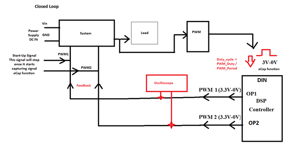
The code is attached here:

Please suggest accordingly.

Thanks

Regards

Arsalan

  • Hi Arsalan,

    eCAP's one shot and continuous are two different modes. One shot allows you to capture a signal one time based on when you re-arm the capture. Continuous allows you to capture the signal without the need to rearm the eCAP module. 

    Once armed, the eCAP module waits for 1-4 (defined by stop-value) capture events before freezing both the Mod4 counter and contents of CAP1-4 registers (time stamps). Re-arming prepares the eCAP module for another capture sequence. Also, re-arming clears (to zero) the Mod4 counter and permits loading of CAP1-4 registers again, providing the CAPLDEN bit is set.

    In continuous mode, the Mod4 counter continues to run (0->1->2->3->0, the one-shot action is ignored,
    and capture values continue to be written to CAP1-4 in a circular buffer sequence.

    Best,

    Ma

  • Hi Ryan,

    Thanks for your reply.

    It means in the code at line 279, I am using continuous mode which doesn't require re-arm procedure. Therefore, I should remove the Re-arm procedure at line 373, is that right? and then will check again during the testing whether it misses the rising/falling edges at several iterations or not

    and also with this assumption,  I can rely on that both modes(continuous/one-shot) captures the incoming pulse signal (either filtered or unfiltered)  and It shouldn't miss the edges in anyway. Also my system shouldn't gets halt or stop either it is being open or closed.

    The code is attached here:

    Thanks

    Regards

    Arsalan

  • It means in the code at line 279, I am using continuous mode which doesn't require re-arm procedure. Therefore, I should remove the Re-arm procedure at line 373, is that right? and then will check again during the testing whether it misses the rising/falling edges at several iterations or not

    Yes you do not have to re-arm during continuous mode. The missing of rising / falling edges, does this occur always when you change your signal generator's output frequency and duty cycle? Does the eCAP eventually output the correct signal?

    Best,

    Ma

  • Hi Ryan,

    Thanks for your reply.

    The missing of rising / falling edges, does this occur always when you change your signal generator's output frequency and duty cycle?

    Not always. but few times. 

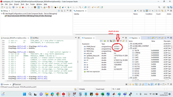
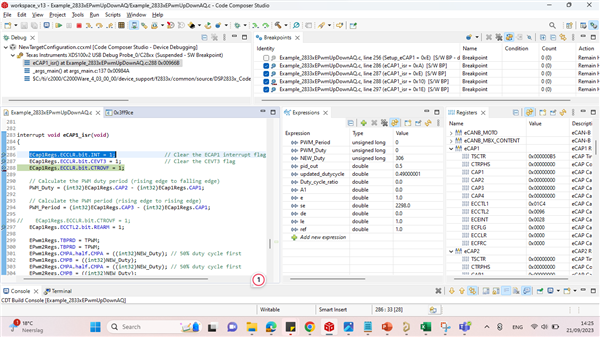
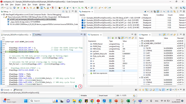
    Missing edges means it starts not taking values or loading if you do the precedure like connect wire and disconnect wire at GPIO24 (eCap1) several times  and then at some point,  it takes no values or it doesn't update the variables (PWM_Period & PWM_Duty) as shown in picture.1 and it stucks at one point (PWM_Period  = 3375511, PWM_Duty = 3375467). no further capturing occurs after the stuck point occurs. whether you connect or disconnect wire no matter at GPIO24.  

    I guess the counter gets full. and it takes no further capturing signals or updating values(PWM_Period & PWM_Duty)  whether you connect or disconnect  wire no matter at GPIO24. Please suggest accordingly to resolve this issue.

    Please see code carefully for the eCap function (Setup_eCAP1(void) ->Line 258-325 and eCAP1_isr(void)->Line 347-373)

    Picture 1:

    Please suggest accordingly to resolve this issue.

    Thanks 

    Regards

    Arsalan

  • Hi Arsalan,

    A counter overflow event (FFFFFFFF->00000000) is also provided as an interrupt source (CTROVF). You could enable this interrupt, clear the overflow flag and then re arm the eCAP module to continue monitoring the signal. I assume if the input signal goes missing or is disconnected while capturing there could be a overflow event occurring causing the invalid captured values. 

    Best,

    Ma

  • Hi Ryan,

    Thanks for your reply.

    So i need to do this in void Setup_eCAP1(void) function ----->

    ECap1Regs.ECEINT.CTROVF = 1;

    ECap1Regs.ECCLR.bit.CTROVF = 1;   

    ECap1Regs.ECCTL2.bit.REARM = 1;

    Right ?

    and I guess no need to re-arm in interrupt void eCAP1_isr(void) function after the PWM_Period/PWM Duty events were calculated. 

    Please review the code accordingly

    Thanks 

    Regards

    Arsalan

  • Hi Arsalan,

    Yes enabling the CTROVF interrupt, you will also need a service routine similar to your eCAP1_isr, OR you can simply check if the CTROVF status flag is active and if it is active you can rearm the eCAP module in your eCAP1_isr. Since it's running continously, the only reason to have the rearm is to reset the capture values and TSCTR. 

    Best,

    Ma

  • Hi Ryan,

    It seems some thing wrong. because ECFLG value 0. CTROVF status flag = 0. and it takes no input values if i supply the voltage at eCap1.it means no capturing. I think (ECFLG .CTROVF) status flag  indicates no event occurred. which means the counter is overflowed( I guess) But i already have done rearm in line 292. It should capture the values ???

    Could you suggest accordingly?


    The code is attached here:

    Thanks 

    Regards

    Arsalan

  • Hi Arsalan,

    It looks like in your code you have not initialized an interrupt to occur when the CTROVF status is set or enabled this interrupt. Once enabled, this will provide you a useful way to know if the CTROVF status has occurred and you can set either a software or hardware breakpoint within this new ISR. Within this ISR you can re arm the eCAP module to reset the counters and continue capturing.

    Best,

    Ma 

  • Hi Ryan,

    Thanks for your reply.

    t looks like in your code you have not initialized an interrupt to occur when the CTROVF status is set or enabled this interrupt. Once enabled, this will provide you a useful way to know if the CTROVF status has occurred and you can set either a software or hardware breakpoint within this new ISR. Within this ISR you can re arm the eCAP module to reset the counters and continue capturing.

    Sorry i am trying to look the interrupt work flow and trying to understand. I have some confusion now. Do i need to initialize interrupt to check CTROVF like the same(for Ecap) in main function (PIE vector table(PieVectTable.ECAP1_INT= &eCAP1_isr;), PIECTRL Register(PieCtrlRegs.PIEIER4.bit.INTx1 = 1;), then function interrupt (interrupt void eCAP1_isr(void))..???? This is all for eCap. Do i need to do same for CTROVF?

    Secondly, Here i did some observations for the breakpoints. Please see below

    I already have enabled the interrupt for CTROVF (ECap1Regs.ECEINT.all = 0x028;) if you see the code if I understand correctly. Below you can see the observations: 

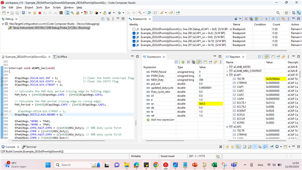
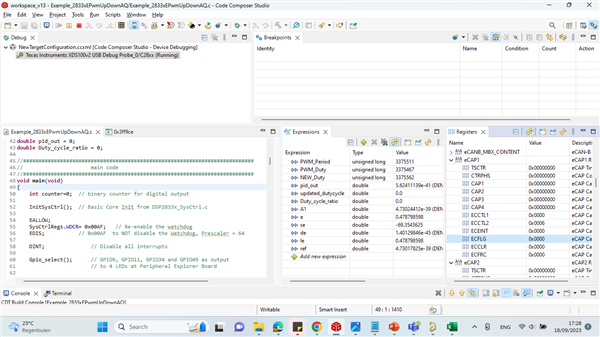
    I checked using breakpoints.  When i set the breakpoints, and no power(eCap1 signal off) is given and then play the green button(debug). The counter (TSCTR) runs continuously. See Picture1

    Picture 1

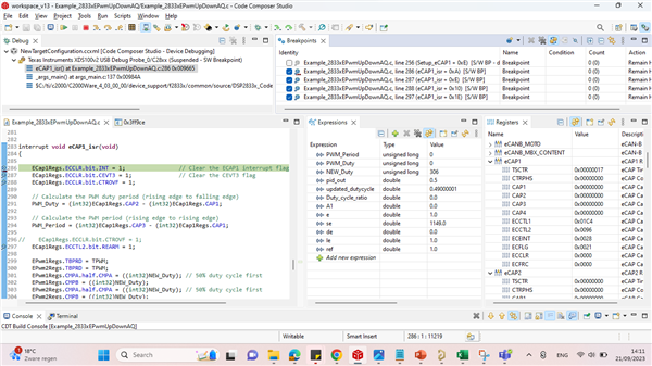
    and suddenly the TSCTR counter stops at one point (0x00017 some time 0x00018) after few seconds and the program stays at picture 2: where ECFLG =0x0021, (see picture 2)

    Picture2

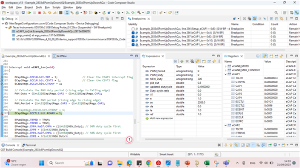
    and then I move to breakpoint step wise until before executing ream -  (ECap1Regs.ECCTL2.bit.REARM = 1;), the ECFLG becomes = 0x001 and then after rearm breakpoint execution, it goes back to above first breakpoint (ECap1Regs.ECCLR.bit.INT = 1;) and ECFLG stills equal to 0x001. (1st loop complete). see Picture 3

    Picture 3

    Then 2nd loop starts (breakpoints points start again when further press debug).

    Now after CEVT3 breakpoint execution (ECap1Regs.ECCLR.bit.CEVT3 = 1;),  the ECFLG becomes 0x000. and See Picture 4

    Picture 4

    and then after rearm breakpoint, the same Picture 1 Counter starts again AUTOMATICALLY and STOPS at ECFLG = 0x0021 same Picture 2. Remember Power is still down (no eCap1 signal)

    Power ON: When i power up the button, the ECFLG becomes =  0x001F and further stepwise breakpoint execution during power up the counter changes  at each step (not continuously) breakpoint execution,  but ECFLF always remains at = 0x001F. (see Picture5)

    Picture 5


    The code is attached here:

    Please suggest accordingly

    Regards

    Arsalan

  • Do i need to intialized to check CTROVF like same in main function (PIE vector table(PieVectTable.ECAP1_INT= &eCAP1_isr;), PIECTRL Register(PieCtrlRegs.PIEIER4.bit.INTx1 = 1;), then function interrupt (interrupt void eCAP1_isr(void))..???? This is all for eCap. Do i need to do same for CTROVF?

    That is correct. You'll need an ISR for the CTROVF interrupt handler.

    The flags that you're showing makes sense of what is happening during capture. The first two pictures means that the capture overflow status had occurred meaning that there was no captured signal. In picture 3-4, you have cleared the OVF flag and it will set the bits within ECCFLG.CTROVF to 0. When you turn on your signal, there is no more overflow flag status bit since there is a signal being captured and the 0x1F means the configured edge events have occurred. (i.e. rising/falling edge captures)

    Best,

    Ryan Ma

  • Hi Ryan,

    Thanks for reply.

    Please check the way for working on your suggestion in terms of code. I will add these lines in my code. Please check the code below and suggest the red missing part for the CTROVF interrupt initialization. 

    Code:>  

    #include "DSP2833x_Device.h"

    ...........

    interrupt void cpu_timer0_isr(void);
    interrupt void eCAP1_isr(void);
    interrupt void CTROVF_isr(void);  // Prototype statements for functions found within this file

    void main(void)

    { ...............

    EALLOW;
    PieVectTable.TINT0  =            &cpu_timer0_isr;
    PieVectTable.ECAP1_INT  =   &eCAP1_isr;
    PieVectTable...-----------...    =      &CTROVF_isr; // Please suggest which PieVectTable should i use for CTROVF ?????
    EDIS;

    .....

    PieCtrlRegs.PIEIER1.bit.INTx7 = 1; // Enable CPU Timer 0 INT
    PieCtrlRegs.PIEIER4.bit.INTx1 = 1; // Enable ECAP1_INT in PIE group 4
    PieCtrlRegs.PIEIER..-----..bit.INTx.---. = 1; // Enable ECAP1_INT in PIE group 4 // Please fill the values here in dash


    IER |= ......----------.; // Please add the value here

    EINT;
    ERTM;

    .....} // main ends

    void Setup_eCAP1(void)

    { ............ 

    ECap1Regs.ECEINT.all = 0x028; // Overflow interrupt enabled

    .......}

    interrupt void CTROVF_isr(void);

     //adding two lines in this interrupt function CTROVF_isr

    {

    ECap1Regs.ECCLR.bit.CTROVF = 1;
    ECap1Regs.ECCTL2.bit.REARM = 1;

    } // CTROVF interrupt ends

    Please rectify accordingly.

    Thanks

    Regards

    Arsalan
  • Hi Arsalan,

    Sorry maybe I misunderstood on what you're trying to implement. I thought you only wanted to use the CTROVF as an interrupt source for the current ISR. 

    Instead let's keep what you original have in this ISR which gets triggered on CEVT3 AND also enable the CTROVF. All you would need to do since we have already change the following bit to 1.


    // bit 15-8 0's: reserved
    // bit 7 0: CTR=CMP, 0 = compare interrupt disabled
    // bit 6 0: CTR=PRD, 0 = period interrupt disabled
    // bit 5 1: CTROVF, 0 = overflow interrupt disabled
    // bit 4 0: CEVT4, 0 = event 4 interrupt disabled
    // bit 3 1: CEVT3, 1 = event 3 interrupt enabled
    // bit 2 0: CEVT2, 0 = event 2 interrupt disabled
    // bit 1 0: CEVT1, 0 = event 1 interrupt disabled
    // bit 0 0: reserved

    Then within your ISR if the ISR gets triggered by the CTROVF event, we can check the flag within an if statement as shown below and re arm the capture:

    interrupt void eCAP1_isr(void)
    {
    
        ECap1Regs.ECCLR.bit.INT = 1;                // Clear the ECAP1 interrupt flag
        ECap1Regs.ECCLR.bit.CEVT3 = 1;              // Clear the CEVT3 flag
        if(ECap1Regs.ECFLG.bit.CTROVF == 1) // Inserted code here
        {
            // This will clear the over flow flag, then rearm for another capture
            ECap1Regs.ECCLR.bit.CTROVF = 1;
            ECap1Regs.ECCTL2.bit.REARM = 1;
            
        }else
        {
           // Calculate the PWM duty period (rising edge to falling edge)
        PWM_Duty = (int32)ECap1Regs.CAP2 - (int32)ECap1Regs.CAP1;
    
        // Calculate the PWM period (rising edge to rising edge)
        PWM_Period = (int32)ECap1Regs.CAP3 - (int32)ECap1Regs.CAP1;
    
    //    ECap1Regs.ECCLR.bit.CTROVF = 1;
        ECap1Regs.ECCTL2.bit.REARM = 1;
    
        EPwm1Regs.TBPRD = TPWM;
        EPwm2Regs.TBPRD = TPWM;
        EPwm1Regs.CMPA.half.CMPA = ((int32)NEW_Duty); // 50% duty cycle first
        EPwm1Regs.CMPB = ((int32)NEW_Duty);
        EPwm2Regs.CMPA.half.CMPA = ((int32)NEW_Duty); // 50% duty cycle first
        EPwm2Regs.CMPB = ((int32)NEW_Duty);
        EPwm1Regs.TBCTL.bit.SYNCOSEL = 1;   // generate a syncout if CTR = 0
        EPwm2Regs.TBCTL.bit.PHSEN = 1;      // enable phase shift for ePWM2
        EPwm2Regs.TBCTL.bit.SYNCOSEL = 0;   // syncin = syncout
        EPwm2Regs.TBPHS.half.TBPHS = TPWM; // 1/3 phase shift
        }


        PieCtrlRegs.PIEACK.all = PIEACK_GROUP4; // Must acknowledge the PIE group 4
    
    }

    The else statement is only executed if there is no CTROVF status.

    Best,

    Ma

  • Hi Ryan,

    Thanks for your reply. It seems working now.  no overflow occurred during my test.

    Thanks

    Kind Regards

    Arsalan