This thread has been locked.

If you have a related question, please click the "Ask a related question" button in the top right corner. The newly created question will be automatically linked to this question.

LAUNCHXL-F28027: How to make pwm Analog input for motorspeed control

Part Number: LAUNCHXL-F28027
Other Parts Discussed in Thread: C2000WARE, MOTORWARE

Hi, 

I am using the launchxl f28027f + boosxl-drw8305evm. 

I am able to control speed of my motor with potentiometer on ADCIN6 (with help from Hal tutorial file).

I now want to use my arduino uno to give the analog input to the ADCIN6 on the launchxl f2802f. The output from the arduino is fixed freq. ( eighter 490 hz or 980 hz) with me applying variable duty cycle to change speed of motor). 

Can you point in the direction of how to read the analog input from the arduino and use it?

BR

Michael

  • Hello Michael,

    For the F2802x device you can refer to the ADC SOC example located in C2000Ware: C2000Ware_5_00_00_00\device_support\f2802x\examples\drivers\adc_soc.

    If you have more specific questions, you can refer to the ADC reference manual chapter here (chapter 6, page 399). If there are specific questions that you have on the ADC, let me know.

    Best regards,

    Omer Amir

  • Yes. How do I configure the ADCIN6 on the f2802 to read the analog input signal (490 hz, variable duty cycle)??? 

  • Hello Michael,

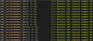
    If you looked at the example I cited within CCS and looked up the declarations of the functions, you can find that the function "void ADC_setSocChanNumber(ADC_Handle adcHandle, const ADC_SocNumber_e socNumber, const ADC_SocChanNumber_e chanNumber)" is used to configure the SOC's channel number.

    To clarify, an SOC of a particular ADC can sample any channel that that ADC has connection to; in this device the ADC can sample the following channels:

    For configuring the SOC to read the input ADCIN6 (I'll assume you're asking to use ADCINA6), you would just need to use this enumeration in the function call. Please look over the example and let me know if you have any other questions on it.

    Best regards,

    Omer Amir

  • My input to the launchxl from the arduino is pwm. How do I make the low pass filter in the launchxl???

  • Hi Michael,

    I don't believe there is any capability to make a low pass filter within this device, so if you want to have a low pass filter you will need to use software to implement this. Unfortunately it looks like this device was created before the FPU was added to our devices, so there is no library support that TI offers that will support this.

    If the throughput of the ADC is of high importance, I recommend using a software implementation since a hardware filter will add impedance to the ADC input when added on the external pin, thus requiring a longer acquisition time for each reading.

    Best regards,

    Omer Amir

  • how do I implement the software??

  • Hello Michael,

    You can look this up online. I've included some links below that I found:

    Depending on the accuracy and smoothness of the filter you need, your implementation may need to be more complex than these.

    Best regards,

    Omer Amir

  • Ok. Is there another way I can change the speed (SPI or UART can be send from arduino)?  I would like it to be as straight forward like with the potentiometer in the Hal file Example.

  • Are you looking to use SPI or UART to communicate the data instead of reading the PWM signal with the ADC? Or am I misunderstanding your question?

  • I am looking for the easiest to control my motorspeed with boost8305 and launchxlsetup???

    It must not be potentiometer, I have already tested that, and it works. I want to use my arduino to give the input to the launchxl. The arduino can give pwm output but also spi protokols.

    I am not a prorogrammer, that is why i am requesting help from TI. Please keep it as simple as possible. 

    Br 

    Michael 

  • Hello Michael,

    To clarify these last couple posts, you're attempting to have the arduino control only the target speed of the motor and nothing else, correct? Additionally, what motor control libraries are you using? From the device, I'm going to assume you're using MotorWare. I highly recommend installing the C2000 Motor Control SDK (MCSDK) as well- this is the SDK that is being actively improved as time goes on, and (very relevant) includes specific examples for each device peripheral on implementation and use.

    • So, the absolute simplest answer is going to be to utilize the F2802x eCAP functionality, at the top of my head. The F2802x peripheral selection is more limited compared to the C2000 MCUs that have been released since.
      • Configure the arduino controller to output a PWM waveform on one pin. This signal will be set as the input into the F2802x eCAP peripheral.
      • Decide the maximum speed you want the motor to run at. For example, let's say that your motor max speed is 80 Hz.
      • The eCAP peripheral can be configured to capture the on-time of an incoming PWM signal- refer to the device TRM chapter 5. Example applications are in section 5.5 and may provide clarity if the initial description is unclear. Effectively, eCAP values can be used to calculate the duty % of an incoming PWM waveform.
      • Set up an interrupt on the F2802x. This interrupt should check the values captured by the eCAP and determine the duty %.
        • If the duty % is, for example, 20%, then set the speed reference value to 0.2*80 Hz (16 Hz) in the interrupt.
        • If the duty % is 100%, then set the speed reference value to 80 Hz.
      • Does this make sense?
    • Alternatively, if the arduino has an SPI, then I would suggest referring to the MCSDK's C2000Ware installation {C2000Ware MCSDK Install Directory}/c2000ware/device_support/f2802x folder. This folder contains specific example implementations of the SPI for the F2802x. It should also contain eCAP examples as well, actually.
      • Set the arduino to transmit and the f2802x to receive. Refer to the examples I mentioned and the device TRM for specifics on how.
      • Set the arduino to periodically transmit the desired speed reference.
      • Set the f2802x to assign the received value to the speed reference variable.

    Regards,
    Jason Osborn