Part Number: TMDSSOLARUINVKIT
Hello Ti Team.
I'm in the BUILD 1 stage - Inverter Open Loop Check and here is my AC sine wave:
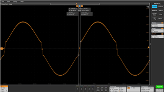
As you can see there is some distortion where the sine wave passes through zero point. I wonder what they are from?
This thread has been locked.
If you have a related question, please click the "Ask a related question" button in the top right corner. The newly created question will be automatically linked to this question.
Part Number: TMDSSOLARUINVKIT
Hello Ti Team.
I'm in the BUILD 1 stage - Inverter Open Loop Check and here is my AC sine wave:

As you can see there is some distortion where the sine wave passes through zero point. I wonder what they are from?
Is this the AC output voltage or current?
Is this generated using the code for micro inverter
Hi Shamim Choudhury. This sine wave I have on my preporuction device and what you see is a voltage measurement with resistance load 200-300 W. What I noticed is that when I increase the load the dissortion is decreased.
Please check your internal reference volt you generated. That has to be good first. Then the PID volt loop controller will track the output to follow the reference volt
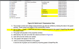
No. This is the sine reference voltage that you generate internally. You can plot that using the datalogger module. Many of our reference designs use that datalogger module.
Your sine reference volt has to be a good sine wave. Then the PID controller will track that to make the Vout sinewave.
Shamim Choudhury can you be more clear with reference voltage generated internally and how to use the datalogger module? I don't quite know what you mean.
Please look at the documentation on similar designs such as
It is all explained for this design. You need to read through doc on different software build levels

