- Ask a related questionWhat is a related question?A related question is a question created from another question. When the related question is created, it will be automatically linked to the original question.
This thread has been locked.
If you have a related question, please click the "Ask a related question" button in the top right corner. The newly created question will be automatically linked to this question.
Hello,
I am having an issue reading Serial Data from other controller into F28062 custom board (also with F28069 LaunchXL board)
When I emulate the same data with USB to serial device I can read all data properly into F28062 but when this particular controller is connected to 28062 then I don't get any data.
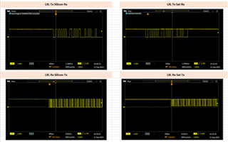
The waveforms for both cases are shown below (first column: F28062 connected to Silicon Labs USB to UART Hub, second column: F28062 connected with other controller board containing ATTiny 3226 Microcontroller)
Can anybody suggest me any solution for this. I am not able to understand what is wrong here.
The ATTiny board has a small diode on its Tx line and hence a small voltage is dropped over that line. In this case (can be seen in second column, bottom picture) the lower voltage is 0.5V but I think this is enough for F28062 to detect the low level, am I right?
This ATTiny board when used with USB to UART hub: I can read all serial data coming from ATTiny unlike in F28062.
Please suggest what can be wrong here.
Hi Rohit,
Thanks for your question. Looks like the waveform on the right (ATTINY) is not properly low or "zero" during bits. It is always high, see image below pointing out the issue. So something is wrong with either the output of ATTINY, or with the board ATTINY is on (maybe it's missing a pullup on the TX pin? Or pullup is too strong?).

Regardless, the output from that ATTINY is likely unreadable due to the fact it seems to not never be fully "low" or "zero" at any point. It looks like it's both 0 and 1 at the same time in those scope images.
Regards,
Vince
Hello Vince,
Thank you for your message and suggestion.
Based on your inputs I debugged this further and have got below observations and comments
1. Yes, there is no pull up on Tx line.
2. In the image in which you have drawn the arrow, you can see the waveform already. The top yellow line could be due to improper oscilloscope settings
3. I replaced F28069/62 board with serial USB converter (Silicon Labs CP210x USB to UART Bridge) to communicate with this ATTiny Board and found that I can read the data from ATTiny without any issues, snapshot below: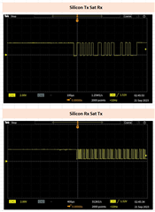
To summaries the data until now: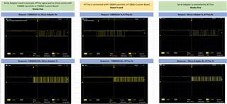
You comments please.
Rohit,
Thanks for the clear and concise debug on this, much appreciated and well done.
Definitely a strange issue because if the Serial adapter is working when transmitting to C2000, I would expect ATTINY to also be able to do the same.
I know I asked this before, but have you tried connecting a weak pull-up resistor (maybe 10k to start with) to both TX and RX of the C2000 device (or ATTINY, whichever you prefer)? Our output driver does not always force high between bytes and that could be why ATTINY cannot understand the signal. And vice versa, if the ATTINY doesn't have a pull-up resistor on TX.
Basically, the scope capture noise you are talking about I don't think is because of Oscilloscope settings.
The reason I am thinking this could be it is because most serial cables have these pull-up resistors on TX and RX lines built in. That's why the cable is working with BOTH devices (which are both missing pullup resistors). But the devices can't talk to each other.
Regards,
Vince
Hello Vince,
Thank you for your message. Makes things even more clearer.
While reading above reply of yours I thought for a moment that I make thing clear (if misunderstood by any chance) which is as below (also acts as summary):
1. Serial Adapter communicates with both LaunchXL and 28062 Custom board without any issue. I am able to Tx and Rx the messages and decode them in my Simulink code.
2. ATTiny Board doesn't communicate with LaunchXL or 28062 Custom board. In this case C2000 board can transmit serial data which is received by ATTiny board, recognized and replied correctly too if observed on oscilloscope. It is just that C2000 board is not able to recognize it. Added further comment on this in last comment of this message.
3. ATTiny and Serial Adapter comm works very well similar to point 1.
Hence, your observation makes more sense when you say that in point no. 2 either device doesn't have pull ups on its comm lines and hence no communication. Serial adapter works with both ATTiny and C2000 board and this is because Adapter might has pull up inside.
I will now try adding pull up on both lines and check the communication again (on case explained in point no. 2), don't you think the pull up will cause the whole waveform to up shift on voltage axis?
About oscilloscope point you mentioned, I will redo this. Also if you might have observed in the same waveform (bottom waveform in second column) the low level is not actually going to zero. Do you think this could be an issue why C2000 controller is not able to detect zero level?
Thank you
Will update on pull up exercise as mentioned above in next message.
Let me add two more points here
1. With LaunchXL board, I don't see any line driver IC in its circuit diagram but a mux
2. With F28062 custom board please note that there is a driver IC (TXU0204) after microcontroller serial lines
Hi Rohit,
Thanks for follow up!
don't you think the pull up will cause the whole waveform to up shift on voltage axis?
With a pull-up, as long as there is no pull-down resistor also attached to the same line, it won’t shift up the waveform.
That does bring up one side question I have though: is the ATTINY 5V or 3.3V output? Some customers use a voltage divider to change 5V to 3.3V, but that will cause failures too (since a voltage divider will pull to ground between bytes).
column) the low level is not actually going to zero. Do you think this could be an issue why C2000 controller is not able to detect zero level?
Good catch, that will definitely cause an issue of it does not go below the GPIO VIL level in the data sheet. Basically it may not detect a voltage change if it doesn’t go low enough.
“””
1. With LaunchXL board, I don't see any line driver IC in its circuit diagram but a mux
2. With F28062 custom board please note that there is a driver IC (TXU0204) after microcontroller serial lines
“””
Correct. The IC drivers typically do not have a pull-up resistor built in though, so if a pull-up is not added between the C2000 TX and TXU0204, the C2000 TX still may float to zero and pull the line low. So they may end up behaving the same even with a driver.
Regards,
Vince
Hello Vince,
Thanks for further insights. I tried adding 10kOhm pull up but still same behaviour.
Setup snapshots for easy reference
Scenario 1 : This works well. There is no pull up on either Rx and Tx line in C2000 board (Custom F28062 or LuanchXL 28069). The reason it works could be due to pull ups inside serial adapter (Silicon Labs) or that the waveforms with VIL rouching zero or well below VIL of C2000 controller. Please note the serial driver used in C2000 board after microcontroller has pull down at input but nothing on output side.
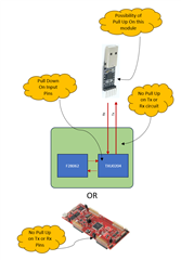
Scenario 2: Does not work. No pull ups on either Rx or Tx lines of ATTiny or C2000 boards.
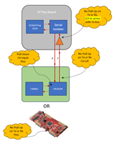
Scenario 3: Works well. This is similar to Scenario 1 where Serial Adapter may have pull ups. The waveform in this case also does not reach zero (VIL) and there is 0.5V gap. Could be due to LED in series with Tx line.
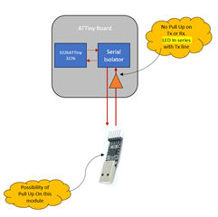
These scenario order same as waveforms in earlier messages.
From above I can make two conclusions:
1. VIL with Serial adapter is higher than 0.5. I checked the datasheet of IC on this adapter where the VIL is shown as 0.6V
2. There could be pull ups on serial adapter PCB.
You thoughts please.
Thank you
Hi Rohit,
I do think your observation of #2 is likely the main reason. Though #1 could also contribute, it may be a combination of the two.
Can you try getting the voltage to zero and see if that helps?
Regards,
Vince