This thread has been locked.

If you have a related question, please click the "Ask a related question" button in the top right corner. The newly created question will be automatically linked to this question.

TMS320F280049C: Using Instaspin for BLDC used as generator

Part Number: TMS320F280049C
Other Parts Discussed in Thread: LAUNCHXL-F280049C, BOOSTXL-DRV8320RS, DRV8320

Hi Everyone!

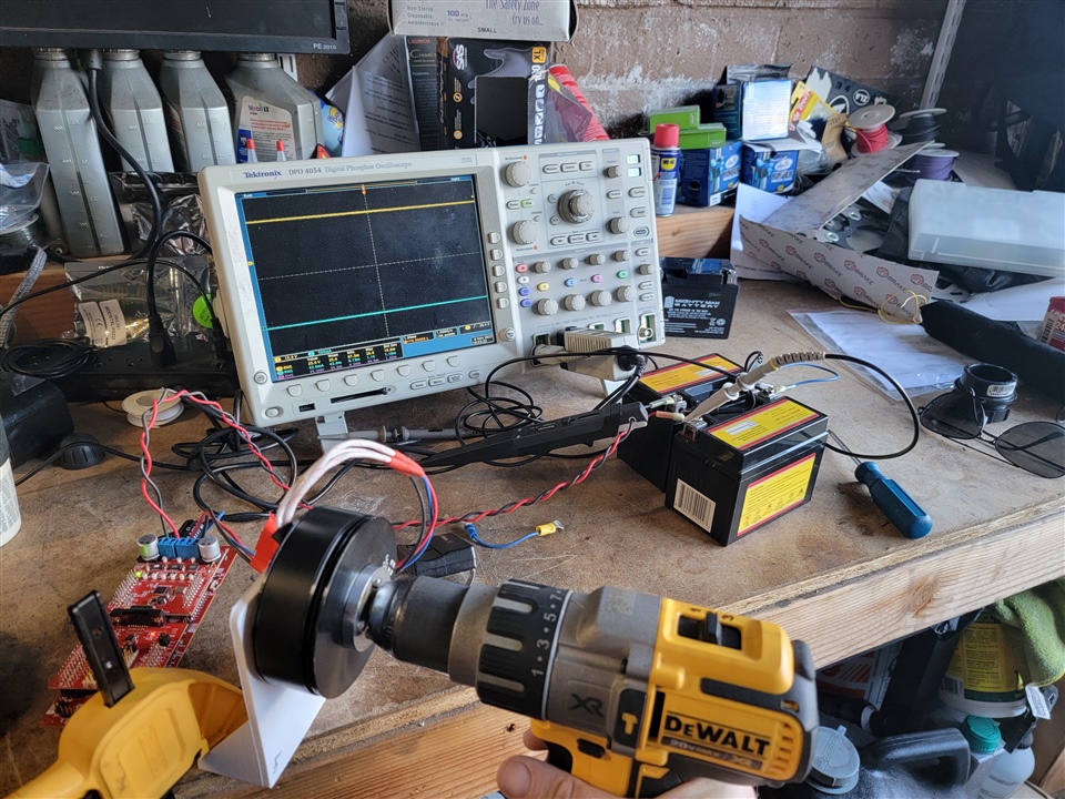
The instaspin libraries and labs are great!  I was able to use a LaunchXL-F280049C and a BoostXL-DRV8320RS with your example code to control a BLDC as a generator!  However, the FAST estimator seems to go unstable in one direction.  Of course this is dependent on the the phase order attached to the board, but for the purposes of this post I'll call counterclockwise the stable direction and clockwise the unstable direction.

I went through the MotorControl SDK InstaSPIN Labs from IS01-IS09, and the software accurately identified the motor, allowed me to close the current/torque loop, and allowed for speed control in a very stable way.  I took lab is09 (flying start) and added a PI instance for DC Voltage control (just like the current and speed PI controllers), added a mode to the motorVars structure called "flagEnableDCctrl", and an if then statement that permitted the PI controller to run and apply an electrical torque counter to the mechanical direction in such a way that the DC link voltage is controlled to a setpoint.  It works great!  I can charge 2 12V lead acid batteries in series to 28V with a spinning motor.  However, this only works when the motor is spinning counterclockwise.  If the motor spins clockwise, the estimation variables in the FAST estimator go unstable.  I'd look through the code of the estimator functions, but these are seem to be hard-coded and inaccessible.

Another modification that I made is in hardware on the DRV8320RS.  I added 2.2mF of capacitance on the DC link near the blue dc link screw terminals, and added additional ceramic capacitance at C2, C3, and C4 of 2 additional caps each, one .1uF and one 1uF.

This thing is awesome, and I'm really happy that TI provides this functionality!  It would be even better if I could get it to run in both directions!  Does anyone have any idea what's happening?

Justin

  • The InstaSPIN-FOC can run the motor with bidirectional rotation without any changes, just need to set the reference speed to a negative value, but we didn't run the machine as generator using InstaSPIN-FOC.

  • Hi Yanming!

    Thanks for the response!  I did notice that in the labs!  The motor can be driven in either direction when you're converting electrical to mechanical energy.  Do you know if the FAST estimator does anything differently when running in one direction vs the other?  I'm honestly a bit stumped about why it would behave differently when converting mechanical energy to electrical energy.

    Justin

  • The FAST estimator may not work well when the machine works within generator mode. We didn't test the generation mode.

  • Hi Yanming!

    Would it be possible to test the FAST estimator in generation mode?  I'd happily write code that puts it in generation mode if you'd test the estimator, I just don't have access to the estimator.

    Justin

  • Sorry, it's difficult to test the FAST estimator always in generation mode directly in our lab, but seems like FAST estimator works well when a fan or blower is working in in generation mode for a short time and the BEMF voltage is lower than the dc bus voltage.

  • I can send you equipment to test this pretty easily.  Would you like that?

  • Can you please show a picture of the test equipment? And how to use the test equipment? We need to know if it's available to be implemented in our lab?Thanks!

  • It may take a few days, but yes, I can absolutely do this!  

  • Sounds good. Thanks!

  • Here's a picture of the setup

  • The only custom parts are the aluminum spindle on the motor and the motor mount.  There's a slight modification to the boostxl motor drive board as described above.  I have a gopro video of how it works uploading right now and I'll try to post that here as well.  @Yanming Luo- do you have all of these things, or would you like for me to send any of it to you?

    Justin

  • Seems like the FAST estimator works well when the motor is running and set an opposite reference speed/current. This case could be similar as you want.

  • You would figure for sure!  Did you see the strange behavior in the video when the motor was spun clockwise rather than counterclockwise?

  • No. You may try to add a ramp control for the torque current, to ensure there is not a high voltage boost on dc bus.

  • You couldn't see the stability in one direction and not the other?  Were you able to watch the gopro video, or is there a better way to get it to you?

  • Not a real generator, just the machine will be in a generator mode when change the reference speed from positive to negative very quickly.

  • I don't understand- could you please reword?

  • Spin the motor to a higher speed with clockwise direction and positive torque current, and then stop the motor and spin the motor with negative current.

  • I still don't quite understand.  Are you saying I'm already doing this or are you telling me to try this?

  • Hi Justin,

    I'm a bit perplexed at how you view the motor is in regenerative mode if the high & low side PWM drives are not first being put into high impedance mode. In order to have true emf power produced the body diodes of the NFETS must freewheel as to rectify AC phase currents into DC.

    So it would seem the only thing being accomplished perhaps is DC bus voltage regulation when the drill speed exceeds the BLDC trajectory set speed user.h. That is why wind turban generators require a resistive dump load as the diode trio in the generator rectifies AC to pulsing DC where the batteries help to further smooth the DC. My view there is no net gain in this scenario only energy being expent powering the drill.

  • The high and low PWM drives are switching- this acts just like a VSI turned backwards into a 3 phase PFC.  Yes, the body diodes conduct sometimes, but the switching turns the system into an AC to DC boost converter.  If you don't care what the speed of the motor is, you can just cascade a DC voltage loop into the existing torque loop and sip power as you like to maintain the dc link voltage.  If you care about what the speed is (as is often the case in wind power), you'll likely have to put the power somewhere (like a resistive load).

    Proof of this is the video above of positive DC voltage and positive DC current- real power is moving.  More proof happens when you put a load in parallel with those batteries and feel the torque increase on your arm as the system pulls more power from the motor :-).

    Justin

  • You just need to enable the FAST estimator always that can work in both motor and generator modes.

  • Are you saying that the fast estimator is being disabled somehow when you spin clockwise instead of counterclockwise?  The portion where the estimator is called is the same regardless of direction and is actually just the same code as what you provide in Lab 6 of the instaspin-foc labs.  Is there a separate thing that can disable the calling of the FAST functions?  I'm willing to try whatever you think is best, I just am having a really hard time understanding what you're telling me to do.  The last thing you said was "Spin the motor to a higher speed with clockwise direction and positive torque current, and then stop the motor and spin the motor with negative current."  I asked "I still don't quite understand.  Are you saying I'm already doing this or are you telling me to try this?", and then we seem to have gone in a different direction.  Would it be possible to answer the question before moving on?

    Justin

  • Yes, the body diodes conduct sometimes, but the switching turns the system into an AC to DC boost converter.

    That seems plausible and wondering have you monitored the NEXFETS temperature while they are boosting voltage or loading in parallel? You sort of lost me at the modification to the speed PI controller and modifying flying start project. TI documentation regenerative mode disables PWM switching from the MCU to the half bridges and considered operational theory in the industry. Seemingly one could flip the U&W leads to reverse the direction of the converter and leave the software as is.

  • That depends on the settings in your project. You need to enable the FAST estimator always. You may refer to the labs supporting flying start function.

  • Are you saying that you think that you think the temperature of the FETs may be to blame for the counterclockwise stable clockwise unstable problem?  You're right in that I can change U&W and make it work the other way, but I'm hoping to figure out a way that it'll be stable in either direction.

    The flying start project has closed loop DQ current control that can start when the motor is already spinning, but doesn't have speed control yet (that shows up in lab 7).  This means that you have a regulator controller you can feed a command into.  All I did was enable everything up to the current control with flying start and installed a DC controller in place of the speed controller.  In lab 7, the speed controller sends a command to the current controller.  In my version, the DC controller sends a command to the current controller.

    As for the "regenerative mode disables PWM switching from the MCU", where did you find that?

    Justin

  • The settings obviously enable the FAST estimator because it works in one direction.  I did refer to the labs supporting flying start, and that's how I got to that point.  What would you need to determine why the FAST estimator works in one direction but not the other?  How would I know if the FAST estimator is being disabled somehow?

  • If the FAST estimator works in one direction, it should be ok in another direction. If the FAST estimator can still estimate the speed and angle of the rotor even when the PWM is disabled to switch off the power to the motor, that means the FAST estimator is enabled always.

  • I agree!  Yet, it doesn't... I will disable the PWM and spin in both directions and see what the Estimator does.  Works?

  • Also, what data would help you see what's going on?  I can watch whatever and give you the data if you think it will help you figure out what is going on.

  • I will disable the PWM and spin in both directions and see what the Estimator does.  Works?

    The original lab can support the flying start that is disabled the PWM, but enable the FAST estimator always. You can check the estimator state as below that could be "EST_STATE_ONLINE". 

    // get the states
    obj->estState = EST_getState(obj->estHandle);

  • As for the "regenerative mode disables PWM switching from the MCU", where did you find that?

    One of several SPI control register codes sent to TI Smart Gate drivers. Some have a code to brake or coast (regenerate) where the bottom NFETS are enabled and the top disabled to brake. Table 15 DRV8320 Smart Gate Driver user guide.

    Coast Write a 1 to this bit to put all MOSFETs in the Hi-Z state.

    Code snip added to LAB_is09 flying start commands SPI enter coast mode, e.g. regenerate! I have not tested the loop though it simply sets coast bit true and checks if coast bit is enabled. Think code does verify bit bang on SPI interface control register.  

            runFlyingStart(estHandle);
    
            //
            // run the speed controller
            // when speed control set true
            //
            if(EST_doSpeedCtrl(estHandle))
            {
                counterSpeed++;
    
                if(counterSpeed >= userParams.numCtrlTicksPerSpeedTick)
                {
                    if(motorVars.flagEnableSpeedCtrl == true)
                    {
                        counterSpeed = 0;
    
    					#ifdef DRV8320_SPI
    							// Check control REG2 bit 2 bool state
    						   if(drvSPI8320Vars.Ctrl_Reg_02.COAST == true)
    						   {
    							   // Disable Coasting NFETS ~high Z state
    							   drvSPI8320Vars.Ctrl_Reg_02.COAST = false;
    					 tryagain_1:
    							   // Write the update
    							   drvSPI8320Vars.writeCmd = 1;
    							   HAL_writeDRVData(halHandle, &drvSPI8320Vars);
    							   // Verify Control REG 2 Update
    							   drvSPI8320Vars.readCmd = 1;
    							   HAL_readDRVData(halHandle, &drvSPI8320Vars);
    							   // Something go wrong SPIB INT6.3/4 IRQ ?
    							   if(drvSPI8320Vars.Ctrl_Reg_02.COAST == true)
    							   {
    								   goto tryagain_1;
    							   }
    						   }
    					#endif
    
                        PI_run_series(piHandle_spd,
                                      estInputData.speed_ref_Hz,
                                      estOutputData.fm_lp_rps * MATH_ONE_OVER_TWO_PI,
                                      0.0,(float32_t *)(&(Idq_ref_A.value[1])));
                    }
                    // Disabled speed control, do Torque Control Coasting Mode
                    else
                    {
                    	// Set coasting torque reference current, 0.0 set above
                    	// Typically inverter is not in High Z state
                        Idq_ref_A.value[1] = IdqSet_A.value[1];
    
    					#ifdef DRV8320_SPI
    							// Check control REG2 bit 2 bool state
    						   if(drvSPI8320Vars.Ctrl_Reg_02.COAST == false)
    						   {
    							   // Enable Coasting NFETS high Z state
    							   drvSPI8320Vars.Ctrl_Reg_02.COAST = true;
    					 tryagain_2:
    							   // Write the update
    							   drvSPI8320Vars.writeCmd = 1;
    							   HAL_writeDRVData(halHandle, &drvSPI8320Vars);
    							   // Verify Control REG 2 Update
    							   drvSPI8320Vars.readCmd = 1;
    							   HAL_readDRVData(halHandle, &drvSPI8320Vars);
    							   // Something go wrong SPIB INT6.3/4 IRQ ?
    							   if(drvSPI8320Vars.Ctrl_Reg_02.COAST == false)
    							   {
    								   goto tryagain_2;
    							   }
    						   }
    					#endif
    
                    }
                }
            }
            // Clear the Idq torque reference
            else
            {
                Idq_ref_A.value[1] = 0.0;
            }

  • Check the estInputData.speed_ref_Hz and estInputData.speed_int_Hz for running the EST_run() function. You may try to set the sign of estInputData.speed_ref_Hz and estInputData.speed_int_H as the rotation direction of the motor, or set these the value of estInputData.speed_ref_Hz and estInputData.speed_int_H to zero when stop the motor.