This thread has been locked.

If you have a related question, please click the "Ask a related question" button in the top right corner. The newly created question will be automatically linked to this question.

TMS320F28065: problem with driving PMSM motor

Part Number: TMS320F28065
Other Parts Discussed in Thread: CONTROLSUITE

Hi forum,

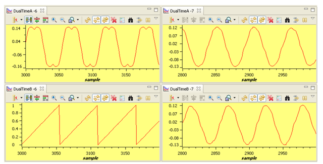
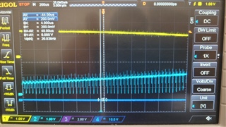
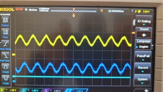
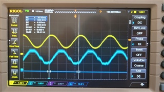
I going to drive a PMSM motor with foc algorithm. I get started with controlSUITE\development_kits\HVMotorCtrl+PfcKit_v2.1\HVPM_Sensorless_2833x project. In the application Level 2b (ajusting PI limits), I must find the maximum values of VqTesting and VdTesting.the problem which I have faced is that the waveforms of the currents are not alike. one of them has got more distortion. since the amplitude of them are equal I guess the current sensing circuit is fine. could please tell me why these two waveform are exactly the same? 

thanks in advance

  • Hi Hamid,

    Does the motor runs normally?

    the problem which I have faced is that the waveforms of the currents are not alike. one of them has got more distortion.

    Did you monitor the current waveform in the debug window like the user's guide (please see picture below)? How is it comparing with the real measurement?

    Thanks,

    Jiaxin

  • Thank you for the reply. 

    motor looks like it is running normally. 

    I am using pwmdac module to monitor the signals. I checked current sensor output, it is almost the same with the out signalof pwmdac. they have shown in the following image. the yellow waveform is the pwmdac output signal and the blue one is the signal measured directly.

    there are a lot of noise on the waveform which its frequncy is exactly two times of ISR_FREQUENCY. I would like to ask you if this can cause any problem for the system and how I can minimize it?

    thanks a lot.

  • Hi Hamid,

    Thank you for the extra information. Do you have external RC filter connected before feeding the PWMDAC signal to the scope? Why there is a phase shift between the actual measured waveform and the waveform given by PWMDAC?

    Thanks,

    Jiaxin

  • Thank you for the reply.

    I am using external RC filter. the yellow waveform is the output of PWMDAC module. 

    and the 180 degree phase difference is because the yellow waveform is multiplied by -1 and it is actually clarke1.As signal which is:

    clarke1.As=-_IQ(((AdcResult.ADCRESULT0)*0.00024414-offsetA)*2))

  • Hi Hamid,

    What is the switching frequency and ISR frequency when you got the below waveform? The noise probably because of the low inductance of motor or low switching frequency.

    For the distortion from first picture (see below). What is the VdTesting and VqTesting you set?

    Thanks,

    Jiaxin

  • Hi Jiaxin,

    I have set ISR_FREQUENCY to 15 (KHz) and the inductance of motor is 0.0065 H. the value of VdTesting and VqTesting were set to 0.1 puand 0.65 pu respectively.

  • Hi Hamid,

    Can you try to reduce the value of VqTesting and see if the current has improvement?

    Thanks,

    Jiaxin

  • Hi Jiaxin, 

    Thanks for the reply and invaluable instructions.
    I changed the motor and with this new motor the current waveforms are completety the same. I guess the old motor is not symmetrical. for new motor the nominal current is about 3.5A. however by increasing VqTesting, when the current consumption (on power supply display) is less than 1Athe current waveform becomes trapzoidal I . since maximum value of VqTesting is going to be used for pid_iq, setting small values for it will lead lower torque. I think I should set VqTesting to higher value. could you please tell me if I am correct?

  • Hi Hamid,

    since maximum value of VqTesting is going to be used for pid_iq

    Please make sure the maximum value of VqTesting will be set for the maximum limit of pi_iq (pi_iq.Umax).

    however by increasing VqTesting, when the current consumption (on power supply display) is less than 1Athe current waveform becomes trapzoidal

    When increasing the VqTesting, what is the value of VdTesting set?

    Thanks,

    Jiaxin

  • Thanks for the reply.

    I have set VdTesting to 0.05 pu while increasing Vqtesting. when VqTesting is set more than 0.27 pu, the current waveforms become trapzoidal and current consumption on power supply display is 1.12 Amps. at this situation when I add some load to the motor the current waveforms becomes sine wave again. I would like to ask you if I should do this test in no-load condition?

  • Hi Hamid,

    I don't think in this stage you need to add an load since current is changed through varying the VdTesting and VqTesting.

    Thanks,

    Jiaxin 

  • Thanks for the reply.

    Could you tell me if there is any relation between max vqtesting and nominal current of the motor? 

    I expect the current consumption of the motor when Vqtesting is set to its maximum eligible value, should be so close to it nominal current. Please tell me if I am correct or not.

    Thanks in advance.

  • Hi Hamid,

    Usually max voltage is suggested to set to 100% of rated motor voltage, which means max VqTesting should be 1pu when Vd is set to 0pu and max VqTesting corresponds the norminal current. However, please pay attention to LL/LN voltage and current RMS calculation according to star/delta connection of your motor.

    Thanks,

    Jiaxin

  • Hi Jiaxin,

    Thank you for the reply. In LEVEL2, when I set VqTesting and VdTesting to 0.5 and 0.05, respectively, the current consumption is about 3A. Moving to LEVEL3, after tuning the PI controllers, when I set IqRef and IdRef to 0.5 and 0.05, respectively, the current consumption is reduced to about 2A, resulting in less torque at the motor output. Could you please confirm if this is okay, or if there's something I might be missing?

    thanks.

  • Hi Hamid,

    Could you please confirm if this is okay, or if there's something I might be missing?

    It should be okay as the motor's dynamic is nonlinear. You could monitor the output of the current controller, i.e., pi_id.out, pi_iq.out.

    Thanks,

    Jiaxin

  • Hi Jiaxin,

    Thank you for the instructions. I have a question regarding Level 3. After tuning the PI controllers, the motor generates some noise. I checked the current of phases A and B (see figure below). In some cycles, they don't appear sinusoidal. I have no idea why this is happening. Could you please tell me the reason behind it? (speed_ref = 0.3, Iqref = 0.5, Idref = 0.3 and current consumption is 0.79A)

    thanks,

    Hamid Kavianathar

  • Hi Hamid,

    Could you try to set Idref=0 and see the performance? In the above experiment, does the pi_id. fbk follow pi_id.ref, and pi_iq.fbk follow the pi_iq.ref, respectively?

    Thanks,

    Jiaxin 

  • thanks for the comment. of course i_id.ref, and pi_iq.fbk follow the pi_iq.ref, respectively. I guess the problem occures when speed_ref is set to high values whitout increasing VdTesting or VqTesting. 

    could you please tell me if these pices of code is correct? because it is not based on my hardware. the shunt resistor and current sensor gain is not used in the code.

    clarke1.As=-_IQ(((AdcResult.ADCRESULT0)*0.00024414-offsetA)*2); 

    clarke1.Bs=-_IQ(((AdcResult.ADCRESULT1)*0.00024414-offsetB)*2);

    the current sensors in my board are connected in inline mode. 

    best regards,

    Hamid

  • Hi Hamid,

    In Level 3, the current is controlled by the PI controller. Thus, the Vd and Vq for modulation are the output of the current control loop. You shouldn't be able to change that through VdTesting and VqTesting anymore.

    clarke1.As=-_IQ(((AdcResult.ADCRESULT0)*0.00024414-offsetA)*2); 

    clarke1.Bs=-_IQ(((AdcResult.ADCRESULT1)*0.00024414-offsetB)*2);

    You need to change the gain and direction of the formula according to your current sensing circuit.

    Thanks,

    Jiaxin