This thread has been locked.

If you have a related question, please click the "Ask a related question" button in the top right corner. The newly created question will be automatically linked to this question.

TMS320F280039C: Manual ACK/NACK of Slave address of PMBus module issue

Part Number: TMS320F280039C

Hello,

I use PMBus module with Manual Slave Address Acknowledgement Mode(MAN_SLAVE_ACK = 1)

following codes are enabled them

// Initial PMBus_A Configuration(PEC enabled, manual address & command, manual ACK for RX byte set to 1)
PMBus_configTarget(PMBUSA_BASE,
PMBUS_TARGET_ENABLE_PEC_PROCESSING |
PMBUS_TARGET_ENABLE_MANUAL_ACK |
PMBUS_TARGET_ENABLE_MANUAL_CMD_ACK |
PMBUS_TARGET_AUTO_ACK_1_BYTES);

// Initial PMBus_A interrupt triggered types
PMBus_enableInterrupt(PMBUSA_BASE,
PMBUS_INT_TARGET_ADDR_READY |
PMBUS_INT_DATA_READY |
PMBUS_INT_DATA_REQUEST |
PMBUS_INT_EOM);

==================================================

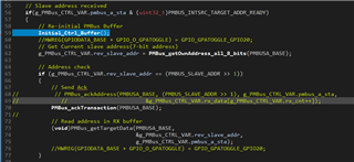
In PMBus_A interrupt ISR, I would use following source codes to send ACK when Slave address received interrupt is happened:

// Get Current PMBus_A State
g_PMBus_CTRL_VAR.pmbus_a_sta = PMBus_getStatus(PMBUSA_BASE);

// Slave address received
if(g_PMBus_CTRL_VAR.pmbus_a_sta & (uint32_t)PMBUS_INTSRC_TARGET_ADDR_READY)
{
    // Re-initial PMBus Buffer
    Initial_Ctrl_Buffer();

    PMBus_ackAddress(PMBUSA_BASE, (PMBUS_SLAVE_ADDR >> 1),
                                       g_PMBus_CTRL_VAR.pmbus_a_sta,
                                       &g_PMBus_CTRL_VAR.rev_slave_addr);
}


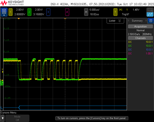
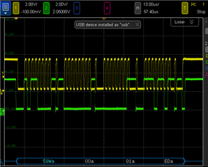
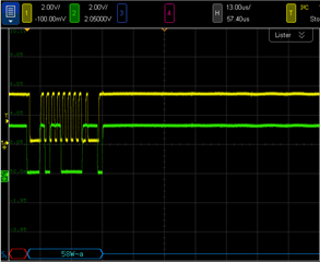
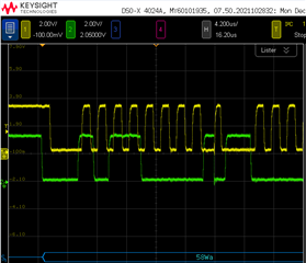
But slave always sends NACk to I2C master.

Does any configuration/action need to check out?

  • Hello,

    Have you scoped the data/clock line when sending the ACK to make sure there is an ACK there? Is there a reason you need to use the manual ACK rather than the default automatic ACK that is used in the PMBus over I2C examples?

    Best regards,

    Omer Amir

  • 1. I need to implement PMBus & FRU function on the same I2C bus, so I need manual method to judge slave address that is for PMBus or FRU

    2. Following diagram illustrate NACK for slave address(Yellow is SCL, green is SDA)


    Another diagram illustrate SCL is held low because I set a break point in "Acknowlodege" of PMBus_ackAddress() 

    When I send a correct slave address

    if((buffer[0] & 0x7FU) == address)
    {
        //
        // Acknowledge
        //
        HWREG(base + PMBUS_O_PMBACK) |= PMBUS_PMBACK_ACK;
    }
    else
    {
        //
        // NACK
        //
        HWREG(base + PMBUS_O_PMBACK) &= ~(uint32_t)PMBUS_PMBACK_ACK;
    }

    It means SCL held low before ACK is sent.

    Following code is initial PMBus_A for reference

    #define PMBUS_SLAVE_ADDR 0xB0 // Basic slave address(8-bit address)
    #define SLAVE_ADDR_MASK 0xEF // Mask bit 4 to implement 0xBx(PMBus) & 0xAx(FRU)(8-bit address)
    
    void PMBus_A_init(void)
    {
        uint32_t moduleFreq = 0U;
    
        // Disable PMBus_A bus first
        PMBus_disableModule(PMBUSA_BASE);
    
        // Initial PMBus_A Module clock
        moduleFreq = PMBus_configModuleClock(PMBUSA_BASE, PMBUS_MODULE_FREQ_MAX,
                                              PMBUS_SYS_FREQ_MAX);
        // Initial PMBus_A support fast mode
        PMBus_configBusClock(PMBUSA_BASE, PMBUS_CLOCKMODE_FAST, moduleFreq);
    
    
        // Initial PMBus_A Target mode(Enable target mode, Slave address mask, and default slave address)
        PMBus_initTargetMode(PMBUSA_BASE,(PMBUS_SLAVE_ADDR >> 1), (SLAVE_ADDR_MASK >> 1) );
    
        // Enable I2C mode
        PMBus_enableI2CMode(PMBUSA_BASE);
    
        // Initial PMBus_A Configuration(PEC enabled, manual address & command, manual ACK for RX byte set to 1)
        PMBus_configTarget(PMBUSA_BASE,
                           PMBUS_TARGET_ENABLE_PEC_PROCESSING |
                           PMBUS_TARGET_ENABLE_MANUAL_ACK |
                           PMBUS_TARGET_ENABLE_MANUAL_CMD_ACK |
                           PMBUS_TARGET_AUTO_ACK_1_BYTES);
    
        // Initial PMBus_A interrupt triggered types
        PMBus_enableInterrupt(PMBUSA_BASE,
                              PMBUS_INT_TARGET_ADDR_READY |
                              PMBUS_INT_DATA_READY |
                              PMBUS_INT_DATA_REQUEST |
                              PMBUS_INT_EOM);
    
    
        // Initial PMBus_A driver control variable
        Initial_Control_Variable();
    
        // Register PMBus interrupt
        Interrupt_register(INT_PMBUSA, PMBus_A_ISR);
    
        // ACK any pending group interrupts
        Interrupt_clearACKGroup(INTERRUPT_ACK_GROUP8);
    
        // Enable PMBus_A interrupt
        Interrupt_enable(INT_PMBUSA);
    
        // Enable PMBus_A module
        PMBus_enableModule(PMBUSA_BASE);

    PMBus_A interrupt code for reference

    void PMBus_A_handler(void)
    {
        // Get Current PMBus_A State
        g_PMBus_CTRL_VAR.pmbus_a_sta = PMBus_getStatus(PMBUSA_BASE);
    
        // Slave address received
        if(g_PMBus_CTRL_VAR.pmbus_a_sta & (uint32_t)PMBUS_INTSRC_TARGET_ADDR_READY)
        {
            // Re-initial PMBus Buffer
            Initial_Ctrl_Buffer();
            //HWREG(GPIODATA_BASE + GPIO_O_GPATOGGLE) = GPIO_GPATOGGLE_GPIO20;
            // Get Current slave address(7-bit address)
            g_PMBus_CTRL_VAR.rev_slave_addr = PMBus_getOwnAddress_all_8_bits(PMBUSA_BASE);
    
            // Address check
            if (g_PMBus_CTRL_VAR.rev_slave_addr == (PMBUS_SLAVE_ADDR >> 1))
            {
                // Send Ack
    //           // PMBus_ackAddress(PMBUSA_BASE, (PMBUS_SLAVE_ADDR >> 1), g_PMBus_CTRL_VAR.pmbus_a_sta,
    //             //                        &g_PMBus_CTRL_VAR.rx_data[g_PMBus_CTRL_VAR.rx_cnt++]);
                PMBus_ackTransaction(PMBUSA_BASE);
    //
                // Read address in RX buffer
                (void)PMBus_getTargetData(PMBUSA_BASE,
                                          &g_PMBus_CTRL_VAR.rev_slave_addr,
                                          g_PMBus_CTRL_VAR.pmbus_a_sta);
                //HWREG(GPIODATA_BASE + GPIO_O_GPATOGGLE) = GPIO_GPATOGGLE_GPIO20;
            }
    
    //        PMBus_ackAddress(PMBUSA_BASE, (PMBUS_SLAVE_ADDR >> 1),
    //                         g_PMBus_CTRL_VAR.pmbus_a_sta,
    //                         &g_PMBus_CTRL_VAR.rev_slave_addr);
        }
        // Receive a data
        else if(g_PMBus_CTRL_VAR.pmbus_a_sta & (uint32_t)PMBUS_INTSRC_DATA_READY)
        {
            // Read slave address again due to complete address can be read in after address ACK sent
            g_PMBus_CTRL_VAR.rx_data[g_PMBus_CTRL_VAR.rx_cnt++] = PMBus_getOwnAddress_all_8_bits(PMBUSA_BASE);
    
            // Command check
            if(g_PMBus_CTRL_VAR.rx_cnt == 1)
            {
                PMBus_ackCommand(PMBUSA_BASE, 0x00, g_PMBus_CTRL_VAR.pmbus_a_sta,
                                 &g_PMBus_CTRL_VAR.rx_data[g_PMBus_CTRL_VAR.rx_cnt++]);
            }
            else
            {
                //Read General data
                PMBus_getTargetData(PMBUSA_BASE,
                                    &g_PMBus_CTRL_VAR.rx_data[g_PMBus_CTRL_VAR.rx_cnt++],
                                    g_PMBus_CTRL_VAR.pmbus_a_sta);
    
                // Send Acknowledge
                PMBus_ackTransaction(PMBUSA_BASE);
    
            }
        }
        // End of Message
        else if(g_PMBus_CTRL_VAR.pmbus_a_sta & (uint32_t)PMBUS_INTSRC_EOM)
        {
            // PEC valid check
            if (PMBus_isPECValid(g_PMBus_CTRL_VAR.pmbus_a_sta))
            {
                // Store PEC
                g_PMBus_CTRL_VAR.ctrl_sta_byte.bits.pec_valid = 1;
            }
        }
    }
    
    // PMBus_A ISR
    __interrupt void PMBus_A_ISR(void)
    {
        PMBus_A_handler();
    
        Interrupt_clearACKGroup(INTERRUPT_ACK_GROUP8);
    }

    PMBus I/O initial

        /* Enable I2C-B on GPIO14 - GPIO15 */
        GPIO_setPadConfig(14, GPIO_PIN_TYPE_PULLUP);     // Enable pull-up on GPIO14
        GPIO_setPadConfig(15, GPIO_PIN_TYPE_PULLUP);     // Enable pull-up on GPIO15
        GPIO_setQualificationMode(26, GPIO_QUAL_ASYNC);  // asynch input
        GPIO_setQualificationMode(27,GPIO_QUAL_ASYNC);   // asynch input
        GPIO_setPinConfig(GPIO_14_PMBUSA_SDA);             // GPIO14 = SDAB
        GPIO_setPinConfig(GPIO_15_PMBUSA_SCL);             // GPIO15 = SCLB

  • Based on your code and your question, I'm assuming you have the F28003x acting as the PMBus controller receiver, and the target is some transmitter. The reason you're not getting an ACK is because your target transmitter is not releasing the SDA line so that the F28003x can pull it low (which is necessary for an ACK). From my understanding the SCL may also be held low to make sure that the ACK can be clocked properly, but the main point is that the data line from the transmitter must be released so that the PMBus over I2C can send an ACK.

    Please make sure that you configured your target transmitter to expect and ACK from the F28003x receiver. If it's reaching the breakpoint that you have in your code for the acknowledgement, that means that the F28003x is trying to acknowledge as expected.

  • Hi Omer,

    clarify the role of F28003x. It acts an PMBus target device. PMBus controller is from an I2C communication card with PC.

    My main question: I use PMBus_ackTransaction(PMBUSA_BASE), set ACK of PMBACK, to try to send an ACK  to controller when F28003x receive a valid slave  address, but F28003x still send NACK to controller.

    I scruple to low some important configuration, please help me check it, thanks.

  • clarify the role of F28003x. It acts an PMBus target device. PMBus controller is from an I2C communication card with PC

    Is the F28003x the target transmitter or target receiver? If it's a receiver, then the transmitter must release the SDA line:

    (From the "Understanding the I2C Bus" application report)

    My main question: I use PMBus_ackTransaction(PMBUSA_BASE), set ACK of PMBACK, to try to send an ACK  to controller when F28003x receive a valid slave  address, but F28003x still send NACK to controller.

    To send an ACK the PMBus peripheral will try to pull the SDA line low. If it's unable to pull it low, unless there is some hardware damage or something is pulling up the SDA or driving it high, the only other reason is because the transmitter has not released the SDA line. This is unlikely something to do with the F28003x device, if you suspect it is then you can test your transmitter with something that you know works in sending an ACK. This needs to be checked before trying to locate some other source for this NACK.

    I scruple to low some important configuration, please help me check it, thanks.

    I'm not sure I understand what you're trying to say here.

  • Hi Omer Amir,

     I use SUB20 to be I2C master device, it can do I2C communicate with other platform(Microchip, ST, etc...) that have manual ACK control via software.

    So I think this communication card has no problem.

    Base on following scoped diagram, it is likely that SDA doesn't be pull low when set ACK of PMBACK by F28003x  

    I suspect my initial configuration of PMBus with wrong. So I would you help to check my source code what I had provided.

    Thanks for your supported.

  • There are a few things you can check that may help me confirm what's happening here. First, I noticed on the SUB20 link you included that the user guide states there are statuses, is this something you can view on your PC? It may help with debugging what's happening

    I also want to confirm that the F28003x is in fact recognizing that the correct address, can you confirm that your code reaches the ISR and that the manual acknowledgement function executes without throwing an error or getting stuck in a loop of any sort? Can you also verify that the address acknowledge bit gets set after the controller sends the target address to the F28003x? Also, can you verify when the PMBus_ackTransaction function executes that the ACK bit in the PMBACK register gets set? You can look at the register bits for a device using the Register view in a CCS debug session (View > Registers).

    I double-checked your PMBus target configuration and it looks correct to me as far as configuring it for target mode with the target address/mask values.

  • Please see following diagram, I set a break point when "Slave address received" of PMBUS_A ISR.

    When I send a slave address to F28003x, FW execute corresponding function.

    And then, received slave address is valid, PMBus_ackTransaction() executes. ACK of PMBACK is set.

    So I think PMBUS_A ISR no any error when F28003x received a slave address

  • And then, received slave address is valid, PMBus_ackTransaction() executes. ACK of PMBACK is set.

    So the register bit is set, but when you scope it at the same time during debug you don't see the ack on the SDA line?

    There are a few things you can check that may help me confirm what's happening here. First, I noticed on the SUB20 link you included that the user guide states there are statuses, is this something you can view on your PC? It may help with debugging what's happening

    Can you also confirm this point I mentioned earlier?

  • So the register bit is set, but when you scope it at the same time during debug you don't see the ack on the SDA line?

    Yes, SDA is still "HIGH" after I set ACK of PMBACK

    Can you also confirm this point I mentioned earlier?

    SUB only provides driver for basic I2C operation. I can't see the source code of driver, so I can't analyze SUB-20 action in futher.

    But experience of other platforms, SDA doesn't hold high after it sends slave address to F28003x

  • At this point I'm not sure exactly what might be going wrong when configuring the F28003x PMBus I2C mode for target configuration, since the address looked to be loaded correctly (although I recommend double-checking this in the Register view in the CCS debug session if you haven't already).

    I will try to ask the design experts to see what may be going on here. It may take some time for them to get back to me, so in the meantime if you have another F28003x device available (or another C2000 device with PMBus on it), can you try to configure it as the controller and see if you can get it to be ACK'd by the other F28003x device? If this works, try reversing the configurations on the two devices. This will be the best way to isolate whether the problem is with the F28003x and if it's just one of them or both of them.

  • Dear Omer,

    Do you have any update?

    Is there consideration when using PMBACK in this case (PMBus target transmitter)?

  • There is no update, I'm still actively working with design experts on this but so far they don't have any theories as to what may be happening here.

    Is there consideration when using PMBACK in this case (PMBus target transmitter)?

    If you're talking about the manual ACK versus the automatic ACK configuration, I'm not sure. I will confirm what may be happening with design experts and let you know.

  • Dear Omer,

    Do you have any update?

  • The design team tested with their own code and found now problems, the manual ACK worked correctly. I took a look at the source code they used and these were their configurations:

        PMBus_enableModule(PMBUSA_BASE);
        PMBus_initSlaveMode(PMBUSA_BASE,0x5A,PMBUS_SLAVE_DISABLE_ADDRESS_MASK);
        PMBus_enableI2CMode(PMBUSA_BASE);
    
        PMBus_configSlave(PMBUSA_BASE,
                          PMBUS_SLAVE_ENABLE_MANUAL_ACK|
                          PMBUS_SLAVE_AUTO_ACK_4_BYTES);
    
        PMBus_configModuleClock(PMBUSA_BASE,10000000,200000000);
        PMBus_enableInterrupt(PMBUSA_BASE,PMBUS_INT_DATA_READY| PMBUS_INT_EOM | PMBUS_INT_SLAVE_ADDR_READY);

    Function called from ISR (I removed parts that weren't relevant):

    void PMBUS_EOM_SLAVE(void) {
        uint16_t ui32Index;
        uint32_t ix;
        uint16_t num_rx_bytes = 0;
        uint32_t status_check =0;
        status_check = HWREG(PMBUSA_BASE + PMBUS_O_PMBSTS);
        if(status_check & PMBUS_INT_STATUS_ADDR_READY)
        {
            slave_addr=HWREG(PMBUSA_BASE + PMBUS_O_PMBRXBUF);
            if(slave_addr==0x5A)
            {
                HWREG(PMBUSA_BASE+PMBUS_O_PMBACK)|=PMBUS_PMBACK_ACK;
            }
            address_ack_int++;
        }
    
        if(status_check & PMBUS_INT_STATUS_DATA_READY)
        {
            HWREG(PMBUSA_BASE + PMBUS_O_PMBACK) |= PMBUS_PMBACK_ACK;
            int_count++;
    
        }
    
        if( status_check & PMBUS_PMBSTS_EOM)
        {
            int_count++;
        }
    }

    I will ask them to try the provided configurations here to see if these are valid or if that's what's causing the issue.

  • Unfortunately it doesn't look like they were able to reproduce the issue. Let me know if this is still a problem for you, and if you've already checked with the configurations in my last post (first code snippet).

  • Hi Omer,

    Thanks your support. I think root cause found.

    I test on LAUNCH-F280039C. SCL connect to EQEP2A of J13 and QEP2 SEL set to 0

    EQEP2A is 5.0V level. But the PMBus master is 3.3V level. it is possible to make NACK state in always

    I change SCL to PIN32 of J4. It is workable.

  • Hi Omer,

    New questions need to clarify:

    PMBus master send a package, "wr_addr(0x58)-cmd(0x00)-data(0x01)-PEC(0xED)", to slave(F280039C). It is success. refer following diagram:

    Then, I try to send same package to slave again. An error is happened. It is "slave address NACK". refer following diagram:

    I double check slave address that F280039C received. It is 0xD8, not 0x58.

    Waveform of address is 0x58. but PMBSHA & PMBRXBUFF is 0xD8.

    Then, I try to send same package to slave again. It is workable.

    The state is OK-FAIL-OK-FAIL switched. If before is OK, next is FAIL.

    Otherwise before is FAIL, next is OK.

    I do an action when EOM interrupt happens: Reset PMBus module. It is always OK. Slave address doesn't happen

    Refer following source code:

    1. PMBus initial:

    void PMBus_A_init(void)
    {
        uint32_t moduleFreq = 0U;
    
        // Disable PMBus_A bus first
        PMBus_disableModule(PMBUSA_BASE);
    
        // Initial PMBus_A Module clock
        moduleFreq = PMBus_configModuleClock(PMBUSA_BASE, PMBUS_SYS_FREQ_MIN,
                                              PMBUS_SYS_FREQ_MAX);
        // Initial PMBus_A support fast mode
        PMBus_configBusClock(PMBUSA_BASE, PMBUS_CLOCKMODE_FAST, moduleFreq);
    
    
        // Initial PMBus_A Target mode(Enable target mode, Slave address mask, and default slave address)
        PMBus_initTargetMode(PMBUSA_BASE,(PMBUS_SLAVE_ADDR >> 1), PMBUS_SLAVE_DISABLE_ADDRESS_MASK );
    
        // Enable I2C mode
        PMBus_enableI2CMode(PMBUSA_BASE);
    
        // Initial PMBus_A Configuration(PEC enabled, manual address & command, manual ACK for RX byte set to 1)
        PMBus_configTarget(PMBUSA_BASE,
                           PMBUS_TARGET_ENABLE_PEC_PROCESSING |
                           PMBUS_TARGET_ENABLE_MANUAL_ACK |
                           PMBUS_TARGET_ENABLE_MANUAL_CMD_ACK |
                           PMBUS_TARGET_AUTO_ACK_1_BYTES);
    
        // Initial PMBus_A interrupt triggered types
        PMBus_enableInterrupt(PMBUSA_BASE,
                              PMBUS_INT_TARGET_ADDR_READY |
                              PMBUS_INT_DATA_READY |
                              PMBUS_INT_DATA_REQUEST |
                              PMBUS_INT_EOM);
    
    
        // Initial PMBus_A driver control variable
        Initial_Control_Variable();
    
        // Register PMBus interrupt
        Interrupt_register(INT_PMBUSA, PMBus_A_ISR);
    
        // ACK any pending group interrupts
        Interrupt_clearACKGroup(INTERRUPT_ACK_GROUP8);
    
        // Enable PMBus_A interrupt
        Interrupt_enable(INT_PMBUSA);
    
        // Enable PMBus_A module
        PMBus_enableModule(PMBUSA_BASE);
    }
    

    2. PMBus ISR:

    void PMBus_A_handler(void)
    {
        // Get Current PMBus_A State
        g_PMBus_CTRL_VAR.pmbus_a_sta = PMBus_getStatus(PMBUSA_BASE);
    
        // Slave address received
        if(g_PMBus_CTRL_VAR.pmbus_a_sta & (uint32_t)PMBUS_INTSRC_TARGET_ADDR_READY)
        {
            // Reset "8-bits address get" state
            g_PMBus_CTRL_VAR.spe_byte.bits.addr_8_bits_get = 0;
    
            // Get Current slave address(7-bit address), doesn't include R/W bit
            g_PMBus_CTRL_VAR.rev_slave_addr = PMBus_Received_Address(PMBUSA_BASE);
    
            // 7-bit Address check
            if (g_PMBus_CTRL_VAR.rev_slave_addr == (PMBUS_SLAVE_ADDR >> 1))
            {
                HWREG(GPIODATA_BASE + GPIO_O_GPATOGGLE) = GPIO_GPATOGGLE_GPIO20;
                // Send ACK
                PMBus_ackTransaction(PMBUSA_BASE);
            }
            else
            {
                // Send NACK
                PMBus_nackTransaction(PMBUSA_BASE);
            }
        }
        // Receive a data
        else if(g_PMBus_CTRL_VAR.pmbus_a_sta & (uint32_t)PMBUS_INTSRC_DATA_READY)
        {
            // Read slave address again due to complete address can be read in after address ACK sent
            if (g_PMBus_CTRL_VAR.spe_byte.bits.addr_8_bits_get == 0)
            {
                // Read 8-bits address
                g_PMBus_CTRL_VAR.rev_slave_addr = PMBus_Received_Address_all_8bits(PMBUSA_BASE);
    
                // Initial control buffer
                Initial_Ctrl_Buffer();
    
                // Set get addressed done
                g_PMBus_CTRL_VAR.spe_byte.bits.addr_8_bits_get = 1;
    
                // Update to data buffer
                g_PMBus_CTRL_VAR.rx_data[g_PMBus_CTRL_VAR.rx_cnt++] = g_PMBus_CTRL_VAR.rev_slave_addr;
            }
    
            // Read data
            PMBus_getTargetData(PMBUSA_BASE,
                                &g_PMBus_CTRL_VAR.rx_data[g_PMBus_CTRL_VAR.rx_cnt++],
                                g_PMBus_CTRL_VAR.pmbus_a_sta);
    
            // Read Data
            if(g_PMBus_CTRL_VAR.rx_cnt == 2)
            {
                // Command check
                if(g_PMBus_CTRL_VAR.rx_data[g_PMBus_CTRL_VAR.rx_cnt - 1] == 0x00)
                {
                    HWREG(GPIODATA_BASE + GPIO_O_GPATOGGLE) = GPIO_GPATOGGLE_GPIO20;
                    PMBus_ackTransaction(PMBUSA_BASE);
                }
                else
                {
                    PMBus_nackTransaction(PMBUSA_BASE);
                }
            }
            else
            {
                // Send Acknowledge
                PMBus_ackTransaction(PMBUSA_BASE);
            }
        }
        // End of Message
        else if(g_PMBus_CTRL_VAR.pmbus_a_sta & (uint32_t)PMBUS_INTSRC_EOM)
        {
            // PEC valid check
            if (PMBus_isPECValid(g_PMBus_CTRL_VAR.pmbus_a_sta))
            {
                HWREG(GPIODATA_BASE + GPIO_O_GPATOGGLE) = GPIO_GPATOGGLE_GPIO20;
                // Store PEC
                g_PMBus_CTRL_VAR.ctrl_sta_byte.bits.pec_valid = 1;
                command_00_data =g_PMBus_CTRL_VAR.rx_data[2];
            }
            else
            {
                command_00_data = 0xFF;
            }
    
            // Re-initial PMBus module
            PMBus_disableModule(PMBUSA_BASE);
            PMBus_enableModule(PMBUSA_BASE);
        }
    }
    
    __interrupt void PMBus_A_ISR(void)
    {
        PMBus_A_handler();
    
        Interrupt_clearACKGroup(INTERRUPT_ACK_GROUP8);
    }

    Please help to check 2 questions:

    1. Why F280039C receive error PMBus address cycle by cycle when master always sends a correct slave address?

    2. Continued Q1, why this issue can be solved by reset PMBus module? Is the method suitable?

  • Then, I try to send same package to slave again. An error is happened. It is "slave address NACK". refer following diagram:

    Is it possible to take a more zoomed-in and higher resolution screenshot? I want to try to see if there's any possible noise or other discrepancies (please also do this for the screenshot where the target address was ACK'd, but just on the target address portion).

    I double check slave address that F280039C received. It is 0xD8, not 0x58.

    Waveform of address is 0x58. but PMBSHA & PMBRXBUFF is 0xD8.

    Can you look at the received target address in the working case and send a screenshot of that? If it's not the same address, is it always 0x6C that's seen as the incorrect address or is the address inconsistent?

    2. Continued Q1, why this issue can be solved by reset PMBus module? Is the method suitable?

    This is more of a question for your system application; if something like this does not affect the functionality of the rest of your system there's no problem in resetting the PMBus peripheral. However, the fact that you have to reset it makes me wonder if there's some flag or status that's not being cleared appropriately which is fixed by a NACK for the target address. Have you verified that all PMBus statuses and flags are the same (besides the NACK) for the OK and FAIL cases?

  • Is it possible to take a more zoomed-in and higher resolution screenshot? I want to try to see if there's any possible noise or other discrepancies (please also do this for the screenshot where the target address was ACK'd, but just on the target address portion).

    Please refer following diagram:

    I set CLK frequency is 400KHZ. It looks the "Data setup time" is shorter than specified of SMBus 3.0

    I zoom-in this part. The "Data setup time" is 110ns.

    SMBus 3.0 defines "Data setup time" is 100ns with 400KHz. It is so margin. It am not sure whether it is root cause or not.

    BTW, how many times of CLK release does after  PMBACK is set?

    Note: I use a GPIO low-drove to measure  time that DAT dirve to low after ACK of PMBACK set 1. It is about 100ns.

    Can you look at the received target address in the working case and send a screenshot of that? If it's not the same address, is it always 0x6C that's seen as the incorrect address or is the address inconsistent?

    See following diagram. The address is 0x58, not 0x6C

    Have you verified that all PMBus statuses and flags are the same (besides the NACK) for the OK and FAIL cases?

    I verify PMBSTS value. It is 0x00143401. it is same between OK & FAIL

  • Nothing looks out of place besides the data setup time you pointed out, I will confirm with the design team on if this may cause the issue you're seeing and why this may be occurring.

  • Hi Amir, 

    Do you have any update from the design team ? 

    Regards,

    Johnny

  • No, I emailed them again yesterday but did not get a response. I've been continually messaging them, but they are delayed because of other projects. I will let you know once I get a response.

  • can you please send me your project? You can either do it here or if you have proprietary information you can send it privately by making a friend request. The designers are not able to replicate this on their end, so I need to give them code that caused the circumstances you saw with your program.

  • Please refer to attached file

    PMBus_test_code.zip

    I double check slave address that F280039C received. It is 0xD8, not 0x58.

    Waveform of address is 0x58. but PMBSHA & PMBRXBUFF is 0xD8.

    I double check this issue, it can re-produce when host write a data 0x8D and then host send a read request with manual mode.

    I try to disable manual address ACK/NACK mode. this issue can't produce

  • Thanks, I'll pass this own to the designers for their simulation.

  • Hello Jen,

    The design team was still not able to reproduce the issue you see with the configurations you provided. Would it be possible for you to run the PMBus as low frequency (100 kHz) to see if the failure is due to timing violations? Can you also share the exact I2C master configurations?